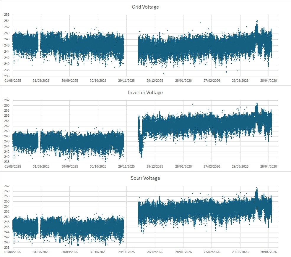
I have been having problems with car charging since last year when GE installed a re-conditioned AC3.0 inverter, and i recently noticed that since that time there seems to be a voltage differential across the consumer unit shown in the plot
The down-interval and new inverter installation is the gap in the middle of the plot. The solar and inverter voltages are pretty much tied together, but differ from the grid voltage CT. The solar CT is mounted on the house side of the consumer unit and the Grid CT is mounted between the zappi charger grid-line out and the smart meter grid input.
Whats suspicious is prior to the new AC3 installation all three voltages were pretty much the same value and car charging was fine. The solar and battery inputs are thro separate RCD's in the consumer unit
Whats might be the cause of this apparent voltage differential across the consumer unit? and could this be promoting the cause of the car charging problems? Or is this a problem with the grid CT?
#2hoggy
A "grid following" inverter will sync to frequency of the grid but not necessarily the voltage depending on what it is doing.
What you aim to do is to use as much of your home produced energy rather than use the grid (that's obviously the point) - but how does the inverter magically give the house it's power instead of the grid when it sits in parallel to it? By increasing it's output voltage ever so slightly above that of the grid. Then your house gets the inverter power instead.
Wanting to export? Well to push the grid "backwards" you increase the inverter output voltage some more - so now not only is the house using everything from the inverter, your now pushing out into your neighbours house instead.
This is what you see here (I'm assuming as it was a replaced inverter the "before" part of the chart is basically no inverter / dead inverter so is purely the grid voltage)
Couple of things -
It's clearly more complicated than my voltage analogy (there's impedance & phase angles and all sorts) but it's the basic measurable outcome of all that
CT Clamps don't measure voltage so wherever your CT meter itself is mounted (the bit with a screen on, such as EM115/GEM110) - it takes the "Grid Voltage" measurements from it's own supply terminals there (so usually the consumer unit voltage) NOT the clamp position.
Your local voltage is being pushed above 253V which is likely why the EV charger is faulting. You need to speak to your DNO and get them to investigate. They will likely tap the local transformer down so your incoming voltage is lower (giving your inverter more headroom to work in)
M
#3Mark Hounslow
The part before the gap (before 29/11/25) was when everything was working fine, car charging, battery inverter. The inverter went down after a firmware upgrade. This early part does not seem to fit your explanation, or the over-voltage differential was much smaller, and hidden in the voltage noise.
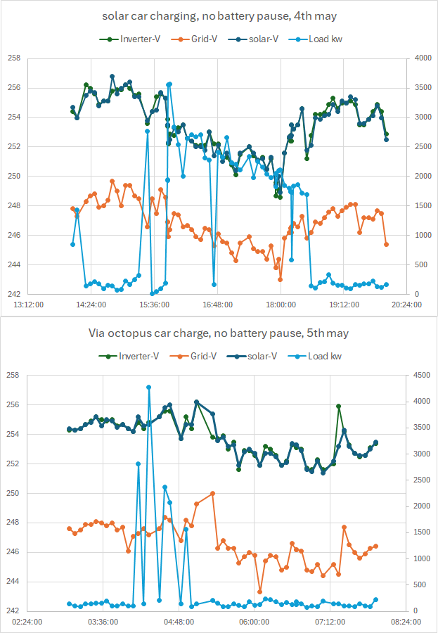
(There is also a 8.2battery replacement just after 27/2/26 causing the smaller decline in all voltages, but it did not make any change to the car charging situation). Setting pause on the inverter stops the car charging problems, but then occasionally car charging seems to work with pause not on. The two voltage-plots below show car-charging slots one successful with solar (upper, with SOC=100%), and one unsuccessful via octopus with power mostly from battery (with many charge-delay stops from the car).
I have been trying the DNO (Electricity North West) with some plots of a fair bit of noise in the grid. However, they have so far declined to do anything, saying i have not demonstrated a problem with their equipment.
Are there any tweaks in the inverter my installer could do?
#4hoggy
How is this all wired? Does everything go through the consumer unit or is solar on one board and EV stuff on another?
When the swapped the inverter did the meters get swapped as well or same ones?
M
#5Mark Hounslow
The solar and inverter have their own RCD's in the main consumer unit. The EV has an RCD in a separate mini consumer unit which is connected to the grid L+N wires between the grid off-switch (house side of smart meter) and the main consumer unit. Hence, the EV takes its power off the grid wires prior to them reaching the main consumer unit.
All earths are connected to a single common earth bar. There is also a 5.2 battery that has not changed.
The AC3 inverter was replaced in Nov 2025, the 8.2 battery in early Feb 2026, both with identical looking units. The units arrived complete, and GE engineers just installed the boxes without changing anything inside that i noticed. The only additional thing is they installed the inverter firmware D0.214-A0.214, which gives me the ability to pause the inverter in a gen-1 inverter, which was not there before the re-replacements.
Before when things have gone wrong, and parts were replaced, GE have done a slow calibration, but they did not do that after the 8.2 was replaced this time, which struck me as different.
M
#6Mark Hounslow
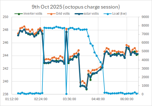
here is an EV charging session before nov 2025, when EV charging was working fine.
R
#7Rubikcube
A competent electrician should be able to check the voltages at various points in the circuit using a meter in a matter of minutes.