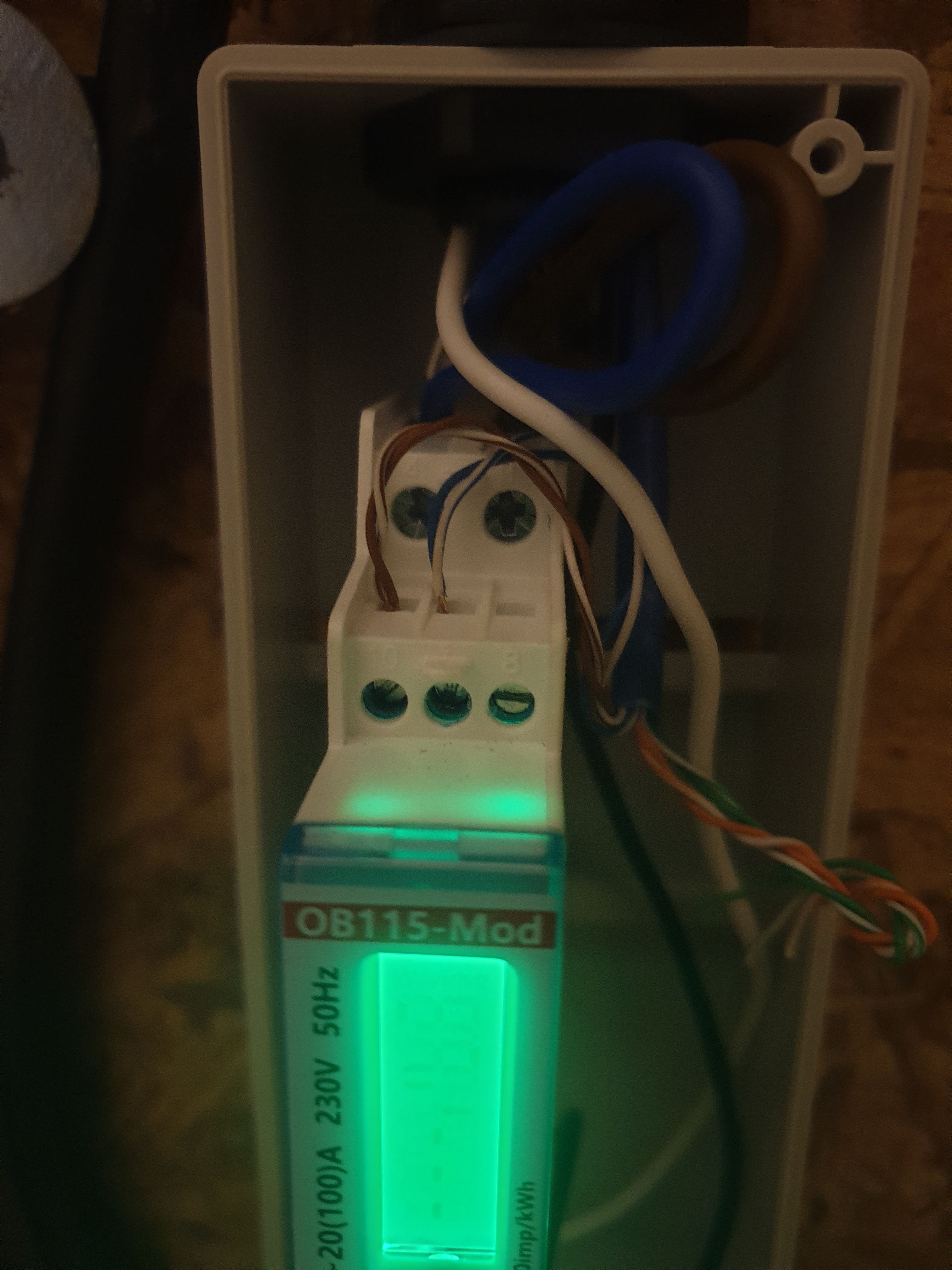
Incorrect EM115 wiring

58 comments started 2023-03-11 last 2023-11-04
CommisioningGivEnergy Products
R
#1 Rubikcube

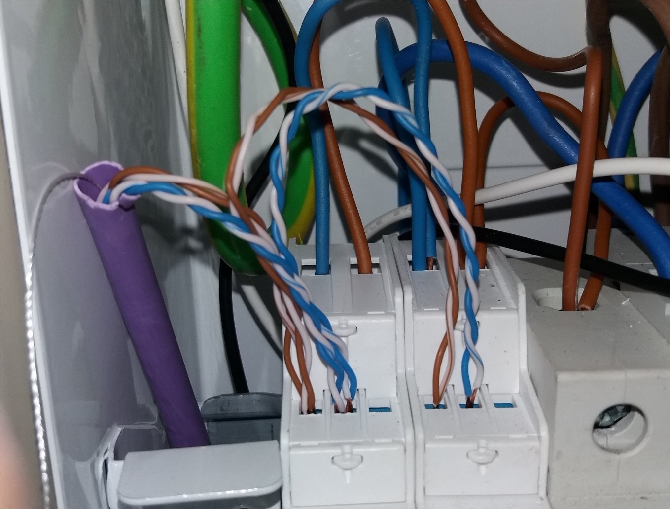
GivEnergy documentation specifies STP cable for data between meters and inverters. Many installers are using cat5/cat6 ethernet cable without issues. However some installers may not be wiring the EM115 communications on a single twisted pair. Using 2 pairs in not better than one! The link should be over a single twisted pair to minimise interference.

The link will "work" however badly it is wired, but incorrect cabling can reduce the response time of the inverter leading to an increased electricity bill for the end user.
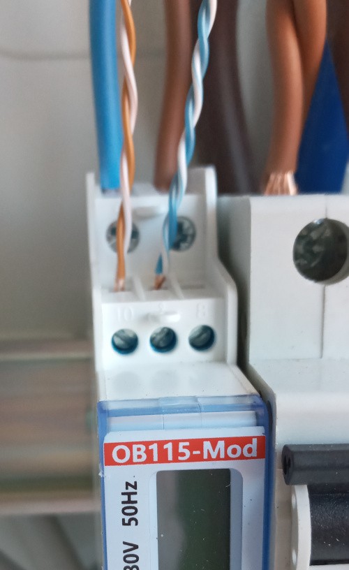
Picture of incorrect wiring.

This is aimed primarily at installers and electricians. If you are an end user, please only remove the cover from a consumer unit if you are competent to do so.

Maybe GivEnergy can pass this reminder to installers when reminding them to set a password on the dongle.

#2 TheDragon (GivEnergy)

VERY wrong indeed.

Ditch one pair.
Use a single pair either blue or orange, or green doesnt really matter. White +ve colour -ve

Adjacent MCD, poor wiring too, exposed copper

#3 TheDragon (GivEnergy)

Rubikcube The new head of training, will add this wiring recommendation to the training. Its currently not in there as explicit as this.

Ive even seen 5A light 2 core cable used, what a mess, it didnt work. Well its blue and brown like the BMS cable.........
Yes thats RS485 and twisted!!!

Use proper RS485 cable, or Cat6 one pair (mine is Cat5 UTP, but only 10m). not a single issue ever.

T
#4 ToothyChris

What are people's view on what to do with the unused twisted pairs, if just one twisted pair is used for the EM115? My RF background makes me think that leaving them floating (i.e. unconnected) would mean that they pick up interference, like an aerial, and then re-broadcast it to the active twisted pair - a bit like a lens focussing light. In other words, it would be worse than if the unused wires are not there.

By earthing the unused pairs you provide a kind of shield, taking that interference away from the active twisted pair, to ground. But I am not sure if that would upset the balanced way in which a proper twisted pair is supposed to work.

Thoughts?

P.S. Congratulations Paul - It will be interesting to see if you (and the other new colleagues) are able to steer the ship back on to a better course.....

#5 TheDragon (GivEnergy)

As the twisted pair would reject common mode interference, Just cut them off, or if you want them for other things, tape up and leave.

There would be no real benefit to earthing them at ONE END only. But wont do any harm

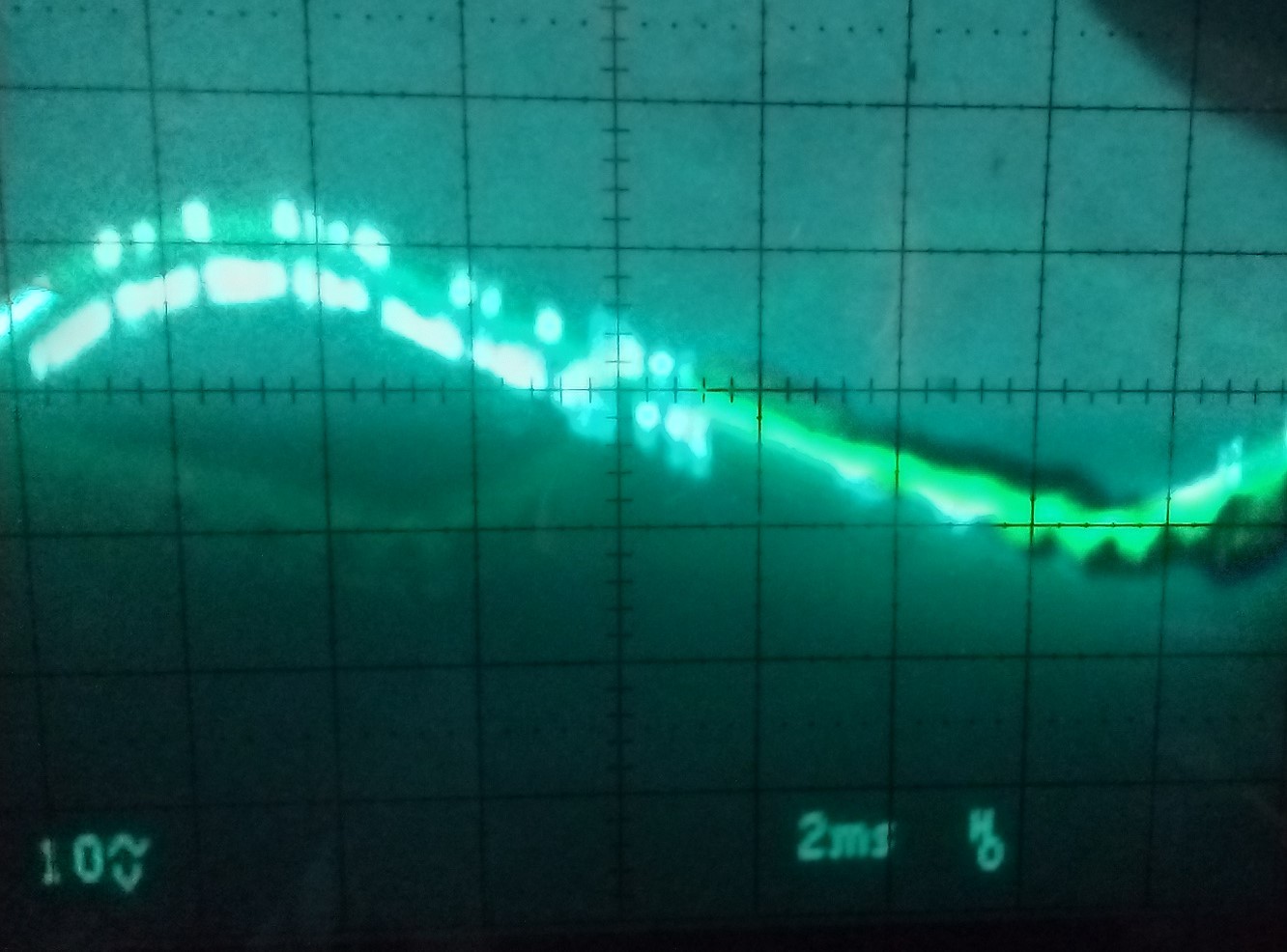
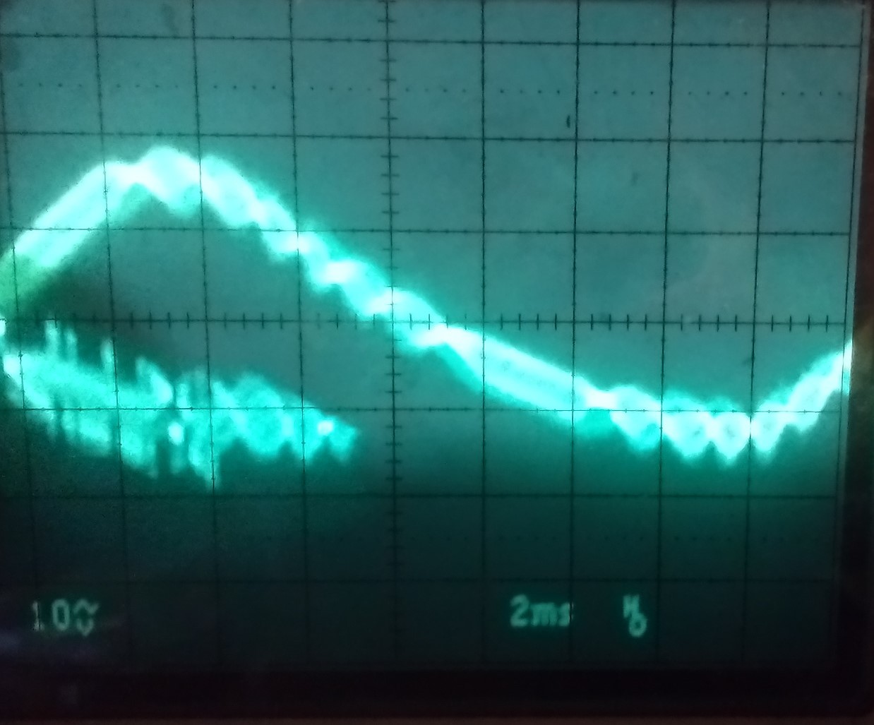
S
#6 Slartibartfast

Correct Modbus wiring.
Use single twisted pair SHIELDED cable. Connect the drain wires together and earth at one point in the system. Tin each wire - ferrules not recommended. Belden RS485 cable (120 Ohm) would be best - however cheaper versions are available (try Alpha).
For low Modbus speeds (9600baud) and lengths less than 100m termination resistors should not be required.

S
#7 Slartibartfast

For anyone interested:

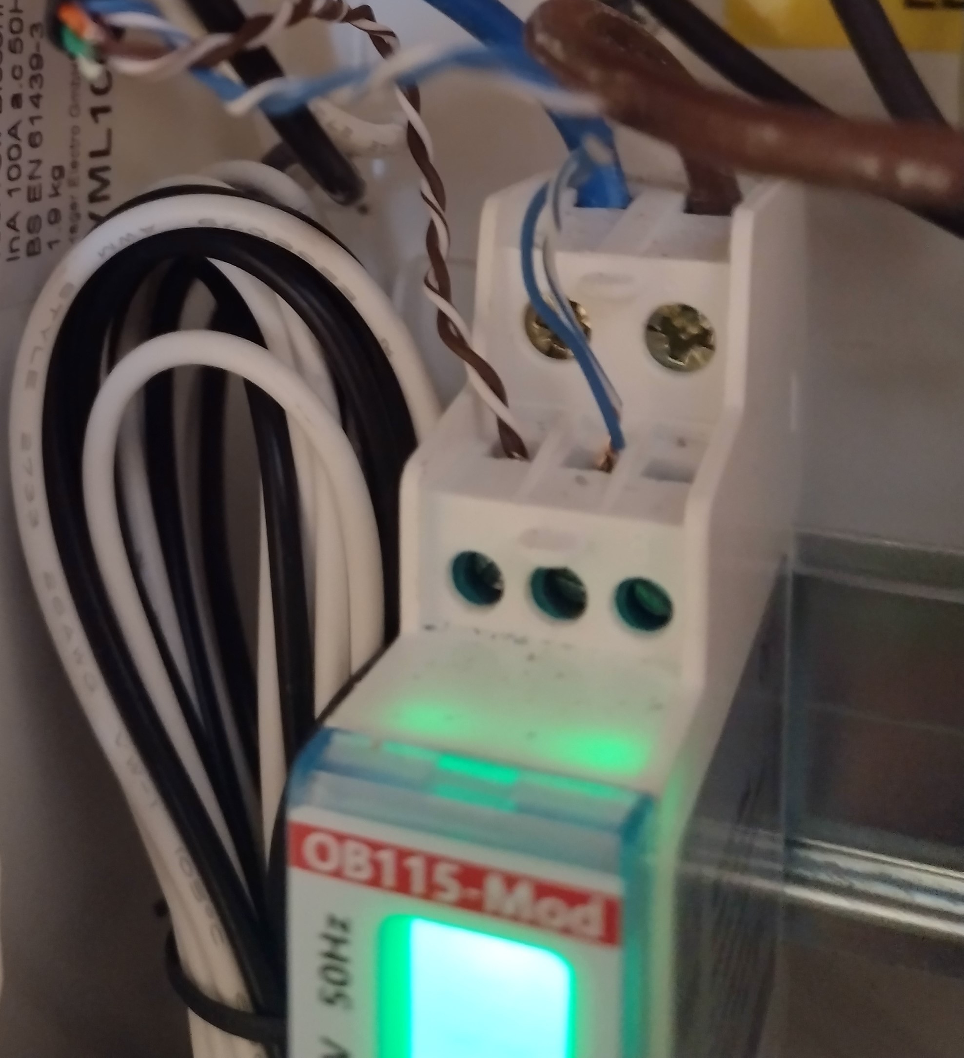
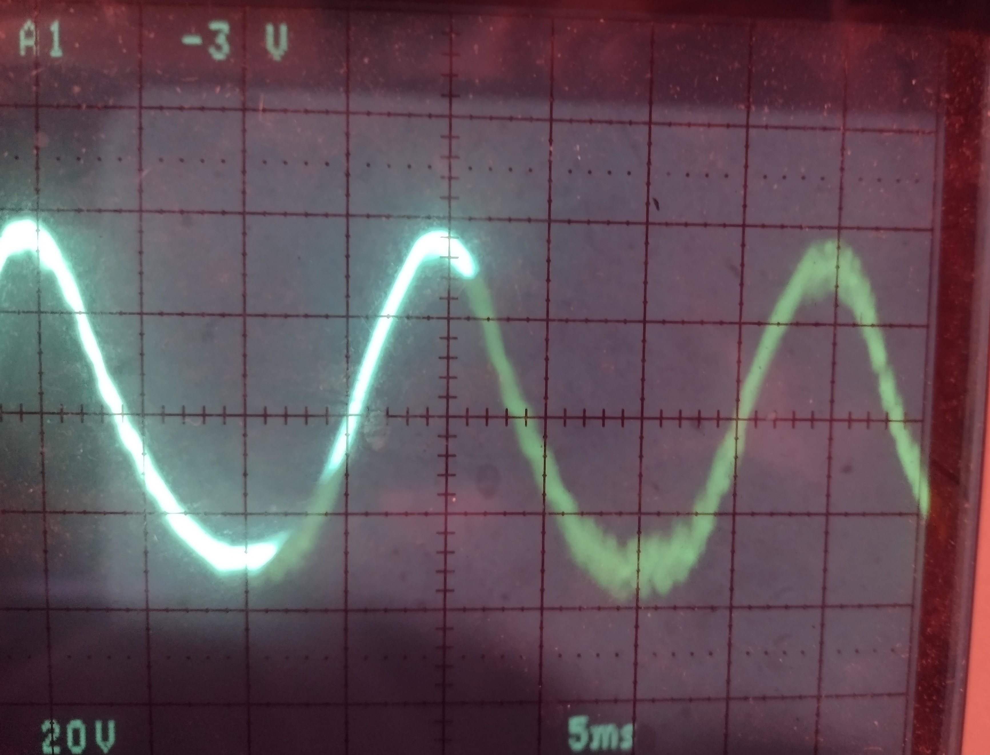
I've seen the AC pickup go up to 60VAC when the house power load is 7kW. Sorry about the photo - no scope camera. The crud you can see is the RS485 signal data - the rest is AC pickup.

The current Modbus wiring - OM115 meter i.e. ID2. ID1 is the same. Later on this week I'll change the wiring and post results.
Why am I bothering - multiple 'Energy Meter comms' errors.

T
#8 ToothyChris

Very interesting Slartibartfast. This suggests to me that the combined output impedance of the EM115, plus the input impedance of the inverter input, must be very high - and hence prone to noise pickup. It would be interesting to see what happens to the relative amplitude of the signal and the 50Hz hum, if you added a load of 5k or 1k across it.

I did try some very crude tests over the weekend on a short bit of twisted pair, both with the scope and spectrum analyzer. For the RF noise visible of the spectrum analyzer, the effect of a grounded conductor close to the twisted pair had little effect. But for the lower frequency noise which was visible on the scope (i.e. stuff which is most likely to interfere with the wanted signal), there was a visible reduction when the close conductor was grounded. Rather a crude test, but it seemed to support my gut feeling about grounding the spare twisted pairs.

Random thought: I understand how a twisted pair reduces common mode (electrostatic) noise, but is the same true of electromagnetic fields (which is probably what your 60V AC is being caused by, if it is dependent upon load)?

(Also, is your 60V AC definitely across the two conductors? I'm just wondering if you are seeing this wrt your scope earth? To put it another way, do you still see 60V AC if you measure the voltage with a high impedance multimeter?)

S
#9 Slartibartfast

If you use a DVM or any cheap meter you can see it - RS485 positive or negative to consumer unit ground. With a couple of hundred Watts flowing through the consumer units it's about 20VAC. Plug the kettle in it goes up to 30ish VAC. RS485 trasceivers will reject most of it. However it may explain the 'Grid Meter fail' notifications.
This is the fourth Grid meter. The last one lasted three days after they connected the wrong CT clamp. It was a GEM meter not an EM115. Now it's an EM115. I spoke to Owen Brothers (OM115). They were 'concerned'.

X
#10 x5toledo

A twisted pair is inherently protective of interference, as currents induced in each of the two cables effectively cancel out.
Cat-5 cable carries four pairs, and the reason they don't interfere with each other is due to different twist rates (evident for the two pairs in the first picture from @Rubikcube ). As TheDragon (GivEnergy) rightly states a single pair should be used for each data link.
From talking with installers some are less certain that others on Cat-5 : one mentioned using two Cat-5 cables for a pair of data connections due to uncertainty whether the four pairs in a single cable could work. As much training and guidance as possible is needed here!

T
#11 ToothyChris

Slartibartfast I may be off the mark here (full Electronic Engineers feel free to step in here, and correct me):

If this signal is being sent over a balanced line, as RS485 appears to be, then it may/will (?) also be floating with respect to earth/ground/chassis. So it would be quite normal to get a high level of mains hum pick up (just like touching the scope probe, with your finger). To see the data signal on your 'scope, in the same way that the inverter will see it, I think you need to use two scope probes on a 2 channel 'scope. One channel would need to be inverted and then added to the other channel, to show you the 'differential' signal (assuming you have that functionality on your 'scope).

Doing this should give you a much better understanding of the difference in the signal, both now (with your non-twisted pair) and later when you have properly wired it. That would be a very interesting experiment, and I would love to see the results on your scope.

(I did a bit of Googling earlier, and it seems that twisted pair does indeed offer protection against both electrostatic and electromagnetic fields).

Toothy (strong on practical electronics, but weak on the theory!)

#12 TheDragon (GivEnergy)

ToothyChris (I did a bit of Googling earlier, and it seems that twisted pair does indeed offer protection against both electrostatic and electromagnetic fields).

Common mode rejection.

RS485 also has termination resistors 120ohm, over 100m runs.
Also can have pull up and pull down too, to prevent a tri state happening, causing oscillation and fake garbled info, seen as a message, wasting time to process it.

I dont know if the EM115 /OB115 have this built in or not.

R
#13 Rubikcube

Simply saying that this issue is down to installer ignorance is a bit like saying plane crashes are caused by gravity. It's true, but it's not the whole picture.

In the original design, the CT clamp was wired directly to the inverter. This was fine in the development lab where the inverter is next to the meter and away from sources of interference. In the real world, it often isn't possible to site the inverter within a couple of metres of the supply, so the OB115 was adopted to allow the inverter to be sited further away. Owen brothers would have asked GE how the meter needed to be configured, and an "ID1, 9600, no parity" became the EM115. Whilst I understand the decision for NO PARITY so as to get the product out the door more quickly, having parity on can detect issues with poor cabling.

In my opinion, the inverter would have been better "field hardened" by using ODD parity and an appropriate error detection algorithm on the inverter. A 2-digit fault code display on the front of the inverter would also be useful. My combi gas boiler has a display and the manual lists 41 possible error codes, some of which would be installation errors.

Accepting that this is not easy, I suggest this an area to be looked at when designing the gen3/gen4/gen5 inverter. If an inverter performs badly due to poor installation, the customer will blame the inverter, not the "nice man" who installed it.

S
#14 Slartibartfast

Guess what - system died at 12:21 yesterday. That's before I had switched to the new wiring. No reply from the installers. I'm trying to avoid the 'you changed the wiring so you've voided the warranty' trap. Even after I showed one of their 'operatives' the problem with a DVM - they still don't think that it is the root cause. I'm waiting for the FIFTH grid meter. Well - I'm assuming that will be their reponse - if they ever respond.
Would be nice if Givenergy said to their installers - if poor sub-standard cabling is found it will void the Givenergy warranty.

T
#15 ToothyChris

Perhaps it might be more beneficial to show them the installer documentation/manual, regarding the use of twisted pair.

A
#16 athresuk

ToothyChris This is another area where the GE installation documentation needs to be improved.

The install manual states :

"Data connection should be twisted pair cable, for example cat5/6 ethernet or Belden type cable"

Well the picture at the top of this thread does indeed use twisted pair cable, just incorrectly, but for anyone not familiar with data cabling wouldn't know this so as far as they are concerned have followed the instructions ........

Working as an Application Engineer I have to write user/installation manuals, unless an installation/use requirement is
explicitly detailed someone will get it wrong.

T
#17 ToothyChris

athresuk Completely agree. Most electricians are probably not that familiar with network cabling or WiFi networks or Access Points - hence some of the issues which arise during installations. I am not a qualified electrician, but I have done the GE installer training, and I was surprised at the lack of detail which was provided. Hopefully, given that GE now appears to have admitted to themselves that something fundamental has to change, they will address the level of training (and documentation, and back-up support) given to their accredited installers.

T
#18 ToothyChris

Hi Slartibartfast . Did you make any progress with your installer, regarding the failed EM115? Have you managed to persuade them that 'twisted pair' is not what they thought it was? I'm really keen to understand what happens when you get an EM115 fitted, with the proper wiring method.....both in terms of the voltage you then see with respect to ground/earth, but also any changes to the error messages you might get.

S
#19 Slartibartfast

Will reply with images tomorrow - one inverter/batt is still down - will require Givenergy to start it. Initiall observation is that the 26VAC pickup (with 3/400W load) is down to less than 2VAC. Will check with and without shield ground.

S
#20 SteveCook

My installer came on Friday to finish the EMS changeover switch.
When I showed him the post and the photo I took inside my EM115 where he has twisted 2 cores together, he said " I have always done it like that and the more copper the better".
He was not going to change it.
I will take the cores out of the EM115.
Does anyone have a photo of the inside of the inverter and know where to take the cover off and I will do that end as well.

R
#21 Rubikcube

Oh dear, what have I started!

Yes, if you change the wiring at the EM115 end, you MUST change it at the inverter to match, or it won't work.

If it's working fine, do consider leaving it alone. Only mess with it if you know you are competent to do so, and make sure you turn the power off!

Don't ask an electrician! Their (part P) training doesn't cover data cabling, and most will probably agree the more copper the better (which is true for power but not data). If you know a telephone engineer, they would be better trained to fix it.

Finally, if anyone does rewire their EM115, please post any results: improved response time, lower import/export in eco mode, less need to restart inverter.

T
#22 ToothyChris

SteveCook It's quite disappointing that the installer is so convinced that he is right, when he is probably wrong. But it's perhaps not surprising, when you think that most installers are electricians who have done a very short GE training course.

Electricians are used to working with power cables at 240V AC, where 'more copper' is indeed better. But signal cabling is a very different matter. After all, would anyone employ a computer network installer to re-wire a house?

T
#23 ToothyChris

Don't feel bad Rubikcube . This is probably a very real issue for a percentage of GE customers, and a (larger?) percentage of installers. The more exposure, the better for everyone (and I've learnt a bit about differential signals too).

#24 hoggy

So what your saying is I shouldn't have used 2 wet shoelaces then...got it.

#25 TheDragon (GivEnergy)

hoggy be fine as long as you keep em wet. Lol.

Don't try this one folks. Leigh is an expert shoelace mason

S
#26 SteveCook

anyone got any pictures at inverter end so I can rewire

T
#27 Tim

SteveCook the cat 5 is terminated in a block connector that plugs into a socket on the underside of the inverter. There’s no covers to remove but probably better to power down the inverter so it doesn’t have a hissy when the meter data is lost. Just check it’s properly seated when you reinstate it.

S
#28 Slartibartfast

Tim
There are two sockets next to each other - one Modbus and the other for a CT clamp. My 'Installers left Modbus plugged into the CT socket...

S
#29 Slartibartfast

Modbus wiring replaced - there is still an AC component - will look into it further. Anyway:

With the shield ground disconnected:

So it looks like shielded cable - with the shield grounded is a good idea. Will keep an eye open for error notifications i.e will it improve things.

S
#30 SteveCook

Rubikcube
Which is the terminal is the positive on this end, and which is the positive at the inverter end.

I can't find any wiring images anywhere

EDIT
For EM115 end
9=minus CENTRE COLOUR
10=plus LEFT WHITE

Facing inverter
Front connector block
minus on right
plus on left

So orientation of cables when looking at EM115 matches orientation of cables when looking at inverter

S
#31 SteveCook

So I unpicked the twisted pairs and separated them and just used blue and blue/white.
Got Electricity Meter Comms Fail on GE inverter notification page.
Swapped polarity at inverter and got same comms error message.
Doubled cores back up to as same condition as installed and it all cleared.
Inverter to EM115 is about 20m.

Not saying the advice above is wrong, but maybe I have a damaged core somewhere?

S
#32 SteveCook

Just remembered the installer had to extend an existing cat5/cat6 to where the inverter was put. He ran new cat5/cat6 and joined the 2 cores he used with a terminal screw block and insulating tape.
I did offer to put RJ45 plugs and RJ45 connector block but he said he did not need that.
I guess when I separated the ends and unpicked then yesterday, they were still joined in the middle

Doh!

#33 dbt85

SteveCook Oh dear. At least it's an easy fix, assuming its easy to get to!

S
#34 SteveCook

Had amusing email exchange with GE.
I asked if they would be happy with me as a Chartered Engineer (Building Services) of 40 years that I untwist the cores at both ends of the cat5/cat6 cable and in the terminal block and put them back in as singles as they recommend into the EM115 and inverter.
They said I must not touch anything as it all must be done correctly by a specially trained and approved installer otherwise the warranty would be affected.

Funny as the original installation was done by a specially trained and approved installer who used 2 cores.

Anyway I have called him and asked him to come back and sort the cable

#35 dbt85

You are more honest than many would have been.

Did you mention to them that the installed who was specially trained and approved had no idea what to do with twisted pairs and that clearly something in the exhaustive training process was missing?

S
#36 SteveCook

That's how the email trail started .
I told them I had seen this post.
I told them I had taken the cover off the EM115 and noted 2 cores had been used.
It then became a bit of a circular conversation about me not touching anything as I was not specially trained rather than the specially trained person who had used 2 cores?!!

T
#37 ToothyChris

TheDragon (GivEnergy)

TheDragon (GivEnergy) VERY wrong indeed.

I have finally managed to get a picture of my EM115 wiring, and I'm disappointed to say that mine is also wired incorrectly. The sparks who did the install is adamant that what he has done is fine, for a short data cable like this. He even implied that some systems had been supplied to him with normal two-core cable for the data.

So, I am now unclear if this is a real issue, which does have implications for system performance (and possibly also EM115 durability, as Slartibartfast's 80V AC mains pickup suggests) or is this actually a non-issue if the cable run is short?

Paul, could we possibly get some good clarity on this from GE and/or the EM115 supplier, as we customers seem to be getting very mixed message about the importance of this, both from GE (your comment above, and the installation manual) vs. the installers (see comments above).

T
#38 ToothyChris

Hi Slartibartfast Just curious to know if you noticed any difference (in either system response or number of error messages), after you re-wired your EM115 to use truly balanced wiring?

S
#39 SteveCook

When I pointed out mine was wired wrong with 2 cores (no comms errors or problems for 6 months), the installer separated the cores and just used singles. Blue and blue/white.
I had a comms fail at different times almost every day for a week.
He put it back as the original install with 2 cores used (brown & brown/white twisted together and blue & blue/white twisted together).
It has been fine for over a week now (plus the original 6 months)
Cable run is about 15m

T
#40 ToothyChris

SteveCook So you seem to be suggesting that it works better when twisted pair is NOT used - is that right?

That's just bonkers....

S
#41 SteveCook

ToothyChris
Chris
It was fine for me for 6 months with two twisted pairs.
When it was "corrected" to a single pair, I had failures everyday for a week.
When it was put back to two twisted pairs it has been fine for a week - so far.
I have no idea and am not going to touch it again

T
#42 ToothyChris

Ah, so your original setup (and again now) is using two parallel sets of properly twisted pairs? I thought you meant that it was wired without the benefit of twisted pairs at all (as seen in all of the pictures above).

So your installer was clever enough to know that a twisted pair was required, but fell into the trap of believing that more copper was better.

S
#44 Slartibartfast

ToothyChris To be honest - still getting comms errors - four so far. All I can say is that the Modbus signals are a lot cleaner. As for the wiring - one of the inverters had two pairs connected - the other just two wires - from two twisted pairs. Before the second inverter was fitted ther was only one Modbus slave (ID1). No comms errors. Now there are three slaves ID1,2 and the slave inverter. I did ask Givenergy the bus ID of the slave inverter. They were just evasive. The reason for changing the wiring - it took the installers three attempts to get it right. Another reason - the GEM I fitted was the fifth meter (possible no: 4 is OK). The system is one year old next week ...

S
#45 Slartibartfast

Another reason - don't let installers get away with it. Modbus/RS485 is a half duplex bus. The xcvrs are designed to drive a 120 Ohm TWISTED pair bus. Unfortunately most installers have no idea about data comms. It should be Givenergy that specifies what cable to use and how to connect it.

K
#46 kram

ToothyChris

What the absolute duck!

T
#47 Tim

SteveCook If your installer really just wants lots of copper, just ask them to terminate the blue and red cores on one terminal and the white/blue and white/red on the other terminal. That way, they will double up on the copper but each data pair is twisted rather than the A and B cores each being twisted.

T
#48 ToothyChris

Tim Exactly, but the logic behind that seems to escape them, so it must be wrong (from their 240V AC perspective).

#49 Stevef1964

Just read this thread - putting my jaw back in place!!!

The way these systems are being installed could well be contirbuitng to all the issues users are suffering.

If you think there are many very similar system cofigurations out there and users seem to be suffering different problems and results, no wonder GE are having problems resolving issues.

Mind you if the training has not been adequate and assumptions made that the installers would all do it the same then GE are also at fault for this.

Years ago when Cat wiring first hit the UK a in the early 90's a company I was working for engaged a number of electricians to install it all in a building. You can imagine what a mess that turned out to be!!! And guess who had to sort it out and continue to work with the installation?

#50 hoggy

As a spark I feel a little attacked!
We aren’t all oblivious…some of us are just as capable of installing 630mm singles as we are Belden. We just prefer the bigger stuff for the monthly weigh in…

#51 TheDragon (GivEnergy)

Single twisted pair is how its recommended. You might get away with it on short runs like this. But no noise isolation.

I use Orange usually, but in theory there all the same, just differeing twist rate and directions, to prevent X-talk

S
#52 Slartibartfast

I would recommend cable with a single twisted pair. Reduces 'choice' and risk i.e. only 50% chance of a cock-up.

A
#53 anglefire

Slartibartfast technically modbus cable is a 1.5pair - with an impedance of 120ohms.

But not all meters have somewhere to tie the 0v to (Rayleigh instruments ones I was setting up yesterday only have 2connections and Schneider Pm511x and similar have 4 terminals for pos neg 0v and screen! Older pm700 have 3.

#54 TheDragon (GivEnergy)

anglefire We could get all teccy with a pull up to 5v too. But probabaly an overkill

T
#56 ToothyChris

TheDragon (GivEnergy) Thanks for taking the time to respond Paul, it really is appreciated. But what we (the paying customers) and the installers really need is a clear an unequivocal answer to the question, which was:

"could we possibly get some good clarity on this from GE and/or the EM115 supplier, as we customers seem to be getting very mixed message about the importance of this, both from GE (your comment above, and the installation manual) vs. the installers (see comments above)."

If I remember correctly, the installation manual says something like 'twisted pair should be used'. This is vague. If there is a real need for twisted pair then the word 'should' ought to be replaced with 'must'. But if it actually makes little difference on short runs (and it does not pose a risk to the EM115, with the higher mains pickup voltage w.r.t. to ground), then we all need to know that as well.

In other words, we need to know if installers should be coming back to rectify this, or if it something which can be safely left as is, without it affecting the reliability of our systems (which in turn impacts GE's warranty liabilities).

If this is not your area of expertise/responsibility, please feel free to highlight this to one of your new colleagues.

J
#57 Jaybee62

With all these systems having coms errors relating back to the data cables and the correct way they should be used, it seems givenergy should tighten there training up and clarify what should be done ?.
My system is a mess, the sparkie "trained" wired the CT straight back to the inverter!!, ( no em115, that "disappeared"), and yes LOTS of Comms errors 🙄, and some !!

T
#58 ToothyChris

Jaybee62 I gave up trying to get any sense out of GE. There are so many different 'holes' in their whole business structure, that banging my head against the wall was a pointless exercise. My system is mostly working OK, and from memory my system is NOT using a proper twisted pair wiring configuration. Asking electricians to understand and implement good practices for data cables was only ever going to be a non-starter, as they have a completely different perspective on wiring (e.g. 'the more copper the better', which is true for mains cabling). I'm not trying to take anything away from electricians, but it's like asking a plumber to set up your new PC.