I wrote a previous post with issues I had, but the situation has changed so I'm starting a new one.
The installer returned to tell me the issues I'd been having were caused by one of the batteries, a firmware issue apparently. One battery was neither charging, nor discharging. I can see from the data both batteries are now discharging.
But, I'm struggling to understand what is going on and hopefully someone can explain it to me.
My house is mostly electric and we are on Octopus Go. We want the 10kW batteries to charge overnight (low tariff) and then the batteries and the PV reduce the grid consumption over the course of the day. We will still expect consumption even during the summer months. We don't want any power going to grid.
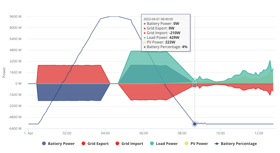
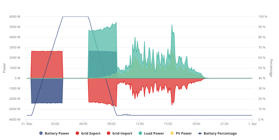
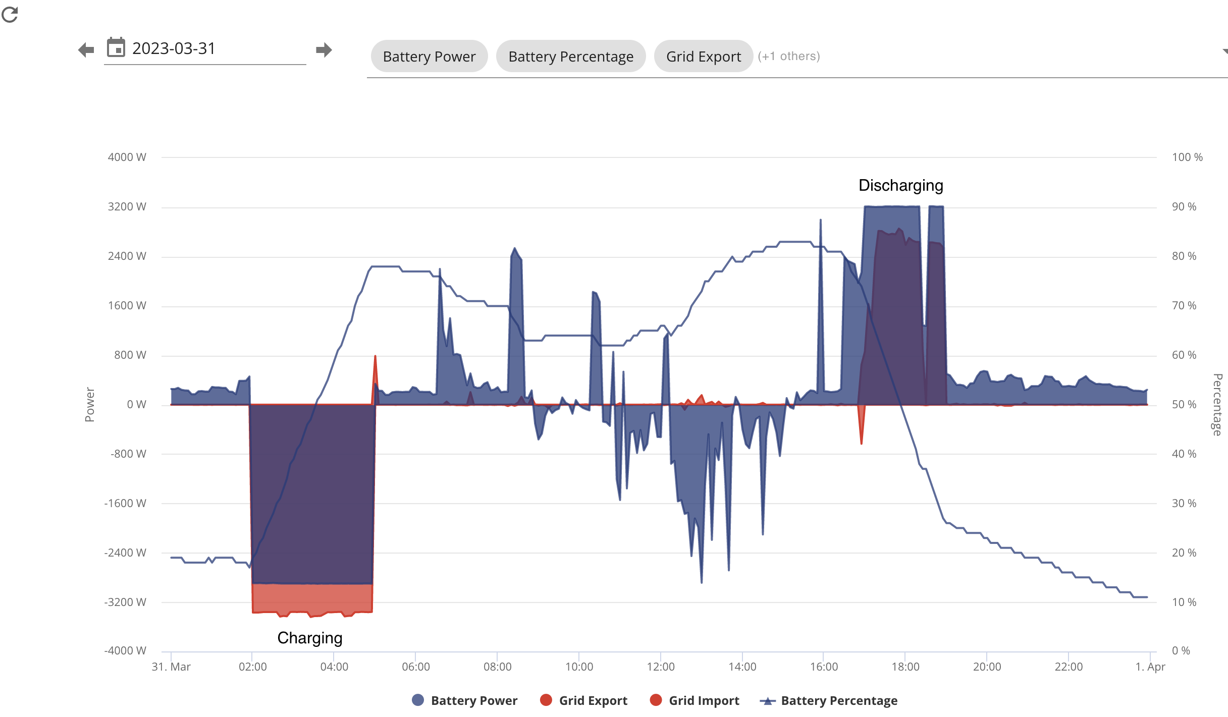
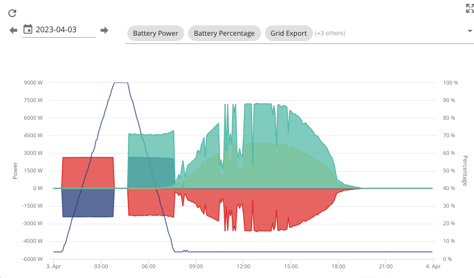
The graphs from my web portal don't seem to make any sense and I just need someone to explain them to me. It looks like the batteries are just dumping all their power into the grid as soon as they are able. I've tried moving the discharge period to see whether I can figure out what's happening but still makes no sense. All info appreciated. I'll put a couple of images below to get started but happy to add others as required.
First one is the overall graph from this morning (after I'd moved the discharge setting for the battery to 8am)
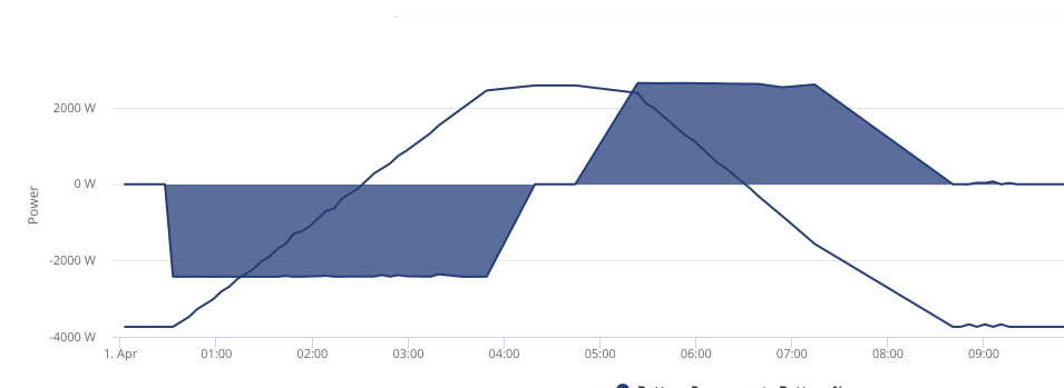
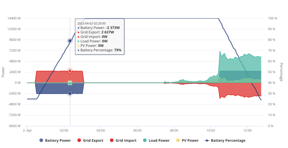
This one is the same period but from the battery only.
T
#2ToothyChris
Calibration cycle?
C
#3cluelesscris
You say you moved the discharge period... How exactly and from what to what? I have never used the discharge period after trying it once and deciding it has a very narrow use case and should be named 'dump my battery as fast as possible'.
P
#4pacemaker
I'm a bit confused by your graph... in the early morning hours you appear to be charging but the red on the graph shows export.
Here's my chart when I charge from grid, the red is below the x-axis showing import...
Z
#5Zakalwe
Don't use the Discharge setting as it will just dump to the grid until the batteries are depleted.
reset to default.
Enable Eco mode.
Set a Timed Charge fornthe Go cheap period with whatever SOC ypu want.
Thats it.
#6Simon_C
Could be the grid CT is wired or clipped on with the wrong polarity, hence showing grid export as the battery is charging?
Zakalwe Bloody set up is awful on Givenergy. Okay, I'll clear out the discharge timer and see what it does. Thanks. I'll post back after tomorrow's fun and games.
E
#9elliott_ness
So now, Timed discharge is off, Eco is on, Timed charge is on (00:30 to 04:30 for Go). Timed Export is off. I'll post the results tomorrow afternoon.
E
#10elliott_ness
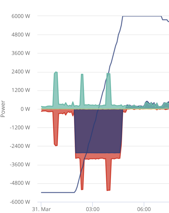
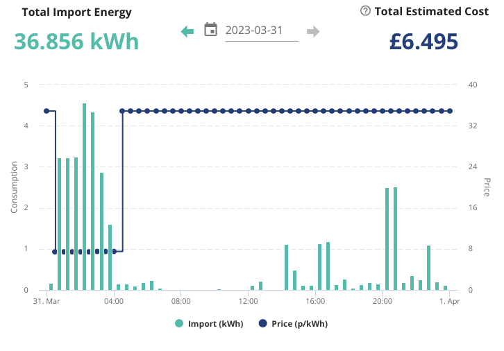
Just noticed something strange. Here is the tariff data from yesterday, followed by the system data. They don't seem to align at all.
P
#11pacemaker
something is very weird with your measurements... could be CT clamp related
E
#12elliott_ness
So, I noticed this morning that the battery wasn't discharging but when I checked the settings, the Eco mode was off. I know I didn't switch it off, but anyhoo. I switched it back on and that is where you can see the battery start to discharge.
What is odd, with this is that it looks like on the graph that the battery discharge adds to the overall load. When looking at the consumption from the tariff data (on previous data I posted further up), this is not happening. Why is the graph showing that?
Anyways, it looks like the problem is resolved now. Thanks for the advice.
Something looks wrong. Your grid import is inverted compared to mine - CT clamp wrong way round?
P
#14pacemaker
kai exactly! I posted same above. OP's screenshot shows it charging the battery with grid export, so something VERY wrong.
E
#15elliott_ness
Well it gets better. With the Eco back on, I thought it was okay, until I checked the next day. Nope. Long way from okay. Now seems to have dumped all the charge into the grid again as soon as the tariff switches over (although it looks like it is charging - obviously there is a reversal in the measure)
Another weird thing I noticed is that the grid import and the pv graphs match almost exactly.
It looks like the PV and the import are just a mirror of each other and the load is a sum of the two.
P
#16pacemaker
I think your CT clamp is the wrong way round personally...
Z
#17Zakalwe
Turn the clamp around and see what happens?
E
#18elliott_ness
I’m not sure where the clamp is. I don’t want to mess too much because I don’t want to invalidate any warranty. I have sent the install company the graph and suggested the clamp is upside down. That wouldn’t explain the graph for the load powe though?
S
#19SimonP
Almost certain the clamp is the wrong way round, it's grid Export that matches the solar generation, not import. Just unclip the clamp, remove, rotate 180 degrees, re-clip onto the wire. The clamp will be on one of the tails (usually the brown one) coming out of your meter. No warranty will be affected and your problems should be solved (I think!). If they're not, just turn it back round and get the installer back.
C
#20cluelesscris
SimonP It's also safe to do as you won't actually be touching any energised mains copper. The clamp is passive, using the hall effect to 'sense' the magnetic flux generated by a current flowing through a cable.
T
#21Tim Adams
I have had 3 x 8.2kw batteries with Hybrid Gen1 inverter for nearly 3 years
recently the batteries were out of sync and had a wide divergence on load charged/discharged.
e.g. 31 Mar
Primary 14%
Batt 1 55%
Batt 2 44%
Also setting for Reserve power was ignored and would discharge through it to 4% (or less). Reserve is needed for EPS reasons.
Decent support from Givenergy resulted in:
Re-calibration of batteries - divergence is now 5%
Firmware update - appears to have resolved Reserve issue
Anyone else with multiple batteries aware of "normal" divergence?
E
#22elliott_ness
SimonP There's no external clamp on the meter tails. There is a possibility it is inside the consumer unit I suppose, or there is a mini consumer unit between the main cu and the feed up to the batteries and inverter in the loft, but I assume that would be too late for a clamp?
E
#23elliott_ness
Okay, so I've opened up the CU and the intermediate fusebox and there's no clamp. Followed the cables all the way back to inverter and nothing.
Now, there obviously is something doing the measurements, but where could that be?
However, there is an Emlite ECA2 unit in the loft and having looked that up, I assume that is what is doing the monitoring? as it is coupled to an EM115 which is boxed so I assume the CT clamp is inside that box.
The CT clamp should be at the point where the mains comes into the house (on the live cable). I didn't have room there so instead they put mine between the meter and the main consumer unit which is apparently also "acceptable" ... anyway - I would think that's where you should look first.
The EM115 has two wires, one black and one white, which connect it to the CT clamp. Follow those wires to the CT and you should be able to unclip it and put it back on the other way round. Just be careful in the vicinity of the CT for bare wires as this will be mains voltage and if you are in any doubt, just leave it for the installer to sort out. The CT itself should be situated ideally between the DNO fuse and the energy supply meter but anywhere between the energy supply cable entering the premises and the first connection to any load (usually a consumer unit). If it's upstream of any consumer unit, it's in the wrong place.
S
#26SimonP
The Emlite meter is, as I understand it, just measuring the amount of energy fed From the inverter into your consumer unit. Without a battery it becomes a solar generation meter and they were (are) read quarterly for the old Feed-in-Tariff systems, but to me it seems redundant on a recently installed system with a smart meter measuring import and export. You can safely ignore it -- I also have one fitted but have never needed to refer to it.
The EM115 has a data link back to the inverter as well as its CT clamp which combined measure everyrhing needed.
I agree with @Tim as to where the clamp should be, electrically. For your system to work correctly it has to be on the feed into the house, before any house load.
E
#27elliott_ness
@SimonP and @Tim Thanks for the input so far. I've done some investigating.
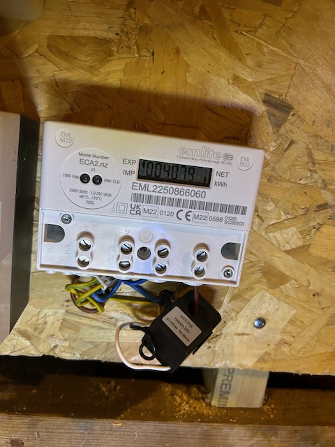
The CT Clamp is on the output of the Emlite meter (in the loft), which feeds the main isolator for the inverter. The input to the Emlite is the feed from the miniature fuesboard for the system which is fed from the main consumer unit (both on the ground floor of the bungalow). So it seems a long way from the ideal of it being connected to the incoming mains before the cu.
So, if I work on the assumption that while not optimal, turning the ct clamp over will make the system have the right loading for the battery, but will it change the problem I have - the batteries charge overnight (correctly) and then just dump all their power into the grid straight away and do nothing to supply the house?
Here's a pic of the CT clamp placement for info.
T
#28ToothyChris
What is your GE setup? AC3 or hybrid inverter?
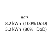
I'm only familiar with a twin AC3 setup, but I believe AC3 needs two EM115 meters (each with its own CT clamp) - one to measure solar generation and one to measure grid import/export. While a hybrid setup only needs one EM115, to measure the grid import/export.
You picture above seems to show a CT clamp measuring the solar generation, suggesting an AC3 system. In which case, you should have another CT clamp to measure your grid import/export.
E
#29elliott_ness
It’s a hybrid and only has the one clamp.
Although the clamp is obviously measuring the power flow, does it also dictate the behaviour of the system? In other words, being back to front is causing the battery to dump the power into the grid when it shouldn’t.
T
#30TX200
The system should know what's coming in from PV if it is DC connected.
So, it sounds like the clamp is in the wrong place. The clamp should be measuring the grid import/export near the smart meter, not measuring the solar.
E
#31elliott_ness
TX200 It is connected to the feed in from the consumer unit to the inverter so in a slightly sketchy way it is in the right line. Seems like that was a bit of a shortcut but it is on the incoming to the system I suppose, just after the consumer unit not before. So it isn’t measuring the actual load of the house only the load of the system.
P
#32Phil_H
The clamp needs to measure the in/out of house to grid, so must be somewhere between dno cutout and consumer unit. After the consumer unit will screw up the inverter operation
T
#33Tim
elliott_ness For a hybrid inverter, if the EM115 CT clamp is between the consumer unit and the inverter, it's in the wrong place. The EM115 CT clamp can only perform its duty if it measures the flow of energy into and out of the premises. Therefore, it needs to be beyond the consumer unit towards the grid. Whether it's between consumer unit, isolator, energy supply meter, DNO fuse or beyond (before any other supplies are taken off to meters), it doesn't matter; just beyond the consumer unit.
Sounds like a call to your installers is needed.
#34TheDragon (GivEnergy)
Tim Sounds like a call to your installers is needed.
I agree, just read this thread. CT is not in the right place. You have a Grid CT monitoring, what looks to be a PV meter from an existing soalr. Or other item requireing metering.
That CT needs to be on the Meter tail, where is can see ALL house load
T
#35ToothyChris
I think this single CT clamp should be round a big thick cable, about a cm in diameter - between the house meter and the fuseboard - but clearly isn't!
E
#36elliott_ness
Thanks everyone. I have requested the installer return earlier this week but they haven’t replied.
Out of interest, apart from the obvious shortcut, is there any reason to fit it this way?
Also, if I turn the ct clamp around will it potentially stop the battery dump? Happy to give it a try and see what happens.
#37TheDragon (GivEnergy)
elliott_ness You could set the discharge power to 0W. that will stop the battery dumping
T
#38Tim
elliott_ness Out of interest, apart from the obvious shortcut, is there any reason to fit it this way?
The AC-connected needs a CT in this position. Could be they got the wrong wiring diagram. Don’t blame them. When did you find out that there were different types of inverters? I only started learning after it was all done and dusted. I had a good experience but that’s not always the case. Sometimes the installers are only one page ahead. That’s the pace of change.
E
#39elliott_ness
TheDragon (GivEnergy) Would that not stop the battery discharging at all?
I guess that will save me having to keep charging it though.
S
#40SimonP
Tim But an installer is paid to know what they're doing.
I don't think turning the clamp in that position around will help much, just cause other problems. It needs to be relocated, as discussed. It measures current flowing through the wire it's attached to, it needs to be somewhere on the incoming mains current path. Putting it on the feed from the inverter (if there is only one inverter!) seems to me idiotic, the inverter already knows what it's putting out, it's in control of that.
E
#41elliott_ness
SimonP It’s not on the feed from the inverter. It is on the feed from the consumer unit to the isolator of the inverter. So it will measure the current flow into the inverter (and out from the inverter) but will not include the load of the house.