EPS for AC

10 comments started 2023-06-05 last 2023-06-06
GivEnergy ProductsAC CoupledBattery
S
#1 Smk82

After a few emails back and forth to GE (thanks for their patience), it looks like I’ll have to live with the EPS limitations:

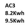
I have a plant setup (2xAC3 and 2x 8.2kwh batteries). I have an EPS setup for one of my AC3.

I had hoped that the EMS would allow both to be set up to continue to work in a power cut. Confirmed however that whilst the EMS would probably still be powered, it wouldn’t provide any benefit due to a lack of sine wave from the grid allowing for the inverters to remain in sync.

No way to connect both batteries to one inverter in this case so I have access to both via the one (despite this being how many systems are configured, I.e one inc, multiple batteries).

So in a power cut situation, I lose 3kw of discharge (ok I can live with it if needed as we are generally a fairly low base load except when cooking etc), and 50% of the installed battery capacity. Only way around it is to a) have split consumer units (one for each, not clear if this would still cause a sine wave issue) or b) stump up for AIO replacement.

Neither of which is palatable. What I don’t get through is AIO (or Tesla PW) both can be stacked behind their gateway and both are AC coupled. So if you have more than one - how do they avoid the sine wave issue?
#2 THALL

Built in isolator? Not sure of the technical details but the gateway must isolate you, island mode. Automatically before switching back. The EPS on the AC3 wont do that. I wanted 2 AC3's with the idea to run my ASHP in the event of the powercut (I get at least 3 each winter) but sadly the loads do not stack, different voltages so as you mentioned above the best I could do is 2 separate 3kw max circuits.

Is sine wave voltage?

T
#3 Tim

THALL Is sine wave voltage?

No it's the shape of the voltage output if viewed on an oscilloscope.

Smk82 No way to connect both batteries to one inverter in this case so I have access to both via the one

No you can't. However, what you could do is have a manual changeover switch to power your EPS consumer unit from AC-connected#1 by default. When the battery is becoming depleted, manually change the switch over to supply the EPS consumer unit from AC-connected#2. You could either have a manual 3-way switch so you can feed the EPS consumer unit from grid/EPS#1/EPS#2 if you need to do inverter maintenance, or a second two-way changeover in series to do the switching between inverter-supplied and grid-supplied. This won't increase the power you can supply but would increase the length of time and thus the energy you could supply to the EPS circuits.

Each inverter EPS would have to have its own protection (fuse/MCB) but otherwise it's just a wiring job.

S
#4 Smk82

Tim thanks, that’s a thought. Any idea why then that the AIO or Tesla (both being AC coupled) can be stacked without seeing the sine wave issues the AC3 would have?

T
#5 Tim

Smk82 Can't be certain but I believe that most hybrid and AC-connected inverters are type tested to G98 (<16A) or G99 (>16A) which specifies that they are "frequency-following". This means that they just follow grid frequency and manage the flow of energy into and out of the inverter. There is another class of microgenerator (think diesel generator) where they don't follow any frequency but have their own built-in controller for standalone use.

The G98/99 type tested inverters all have to disconnect from the grid when the frequency falls outside the specification but they can have a separate "islanded" EPS as long as there's separate earthing arrangements. I'm presuming the Tesla Power Wall and AIO are type tested to another standard or comply with G98/99 by physically separating the house consumer unit from the grid to ensure that the grid cannot be exposed to voltages generated by the Tesla or AIO and have the capacity to power the load on the consumer unit for a period of time.

T
#6 TX200

Smk82 the AIO:

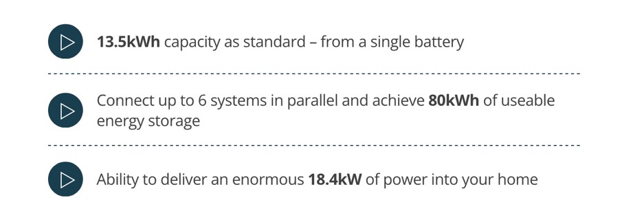
You can join the systems together, but can’t increase the kW output by much. Almost looks like it would be one AIO inverter and five slave batteries???

T
#7 TX200

Actually scratch that. It’s 6kW output for one AIO. 18.4 kW output for six together?

Guess the gateway keeps each extra AIO in sync with the master AIO???

Certainly need a way of getting the other AIOs to follow, unless it’s just each AIO powers a different circuit in the house, but that sounds messy, 6 consumer units!!!???

S
#8 Smk82

TX200 exactly. This is what has me confused. The type thing I didn’t know about. A tad irritated as part of the reason I went with what I did was that I was informed that these were coming and that they would be backward compatible.

M
#9 mrand31

Can one system feed the load with the EPS and the other synchronise to that with it's normal mains input?
If not, why not?

#10 hoggy

mrand31 because it will try and export power into the EPS of the other inverter mostly.