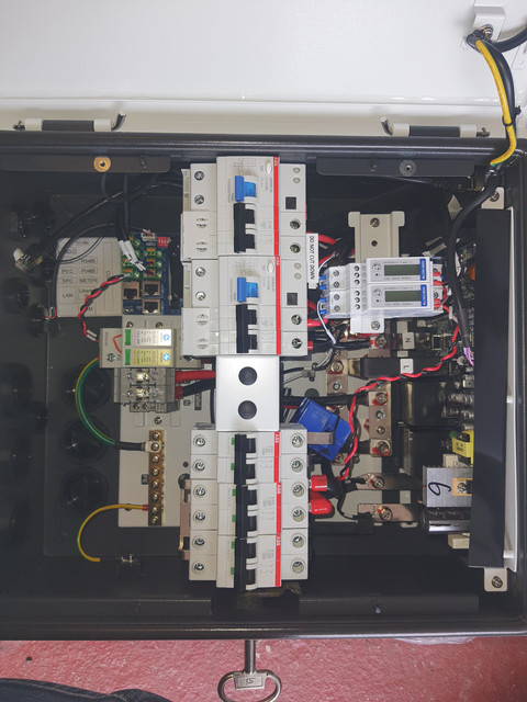
So I have a bit of a disagreement on design (other electricians may have a different stance depending on how you read the regs) so here goes:
The supplied breakers themselves are just standard ABB, I believe System Pro which you can pick up easy enough (RS have them all should you need). You shouldn't really mix brands. That leaves space for another EM115 meter to monitor the EV on its own - this isn't particularly made clear that is the intention from the manual, so one would assume that the portal would be able to separately monitor EV load should you set the EM115 meter to say ID3/4/5 whatever. I have no problem with this bit, neither should your installer.
The parts I do are as follows:
There are live busbars scattered all over where you can pick up the spare supply. They even have spare holes drilled in them, which makes you think "great easy enough let's take the EV supply from there" however they are only drilled on protected gateway side, which seems daft as you'd then be at risk of overloading the AIO, weird things happening with frequency etc as I mentioned before.
To fit it to the grid side you have 3 options -
1 drill the busbar on the grid side. Now I've seen the absolute a£se installers make of the simplest things, and these bars are in an awkward spot. But you can still see the "total" load of the house as there is a CT hiding on the input MCB to the gateway.
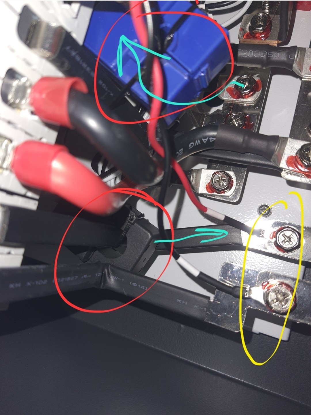
2 install a Henley block on the tails before you connect to the gateway. Easy enough but there's a catch. The gateway grid input has a CT monitoring incoming supply. (Black CT circled, the blue 1 is monitoring load going out from the gateway) so you'd not see the "actual" total house load reported at all anywhere. Not the end of the world I guess.
3 just reuse the terminals used for the EM115 meter supply - again this may be easier, but your breaking factory torqued connections (yellow circle) so this feels off. It also highlights one of my concerns with the design - the Em115 meters are just screwed to busbars with no protection at all beyond a 100A MCB feeding the bar. This is the same for both meters. (GE obviously think this is fine but come on, if I did that there'd be hell on) 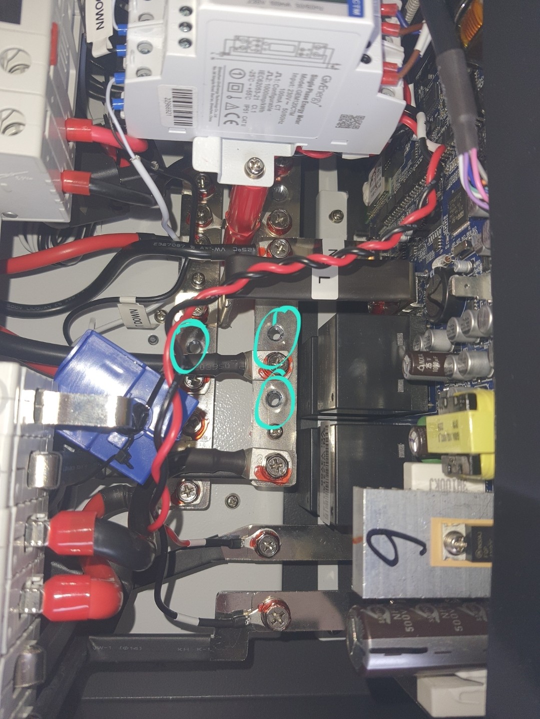
Other issue Preface: maybe I'm being too picky:
The RCDs themselves prefitted for AIO and PV inverter are type AC which depending on install method and the brand of PV inverter you attach adds another layer of complexity.
(And the AIO needs adding to the RCD Declaration document if that is the case to cover installers backs)