W
#1 Wayland
Hi
We currently have a power cut. For some reason we aren't able to draw power from the battery even though it is fully charged. We have only had the system a few months. Any ideas please ?
Thanks in advance

Hi
We currently have a power cut. For some reason we aren't able to draw power from the battery even though it is fully charged. We have only had the system a few months. Any ideas please ?
Thanks in advance
Do you have an EPS system? If not I don’t think it will work
We were told that it would supply energy in a power cut . Is there a way to double check ? Sorry for being dumb!
Your installer should have told you what to do if you do have EPS. There are fully automatic versions, manual whole house ones (what I have) and ones with just a couple of sockets. Probably a big switch with grid-off-eps/battery if it’s manual. You have to have something to isolate your house from the grid or you might electrocute the guys fixing the power cut!
I think an early call to your installer is called for
Thanks so much for the advice
There are 2 plug connectors on the underside of the inverter.
One is power, one is EPS.
If there is only one cabled up then I guess that tells you no EPS.
Look on the portal power dashboard. One of the drop downs for viewing is EPS power. Does that show anything. My EPS is configured as permanently live and generally runs about 250w for fridge, freezer, TV, sky box, router, gas boiler and smoke alarms.
SteveCook thank you so much for this. Really helpful.
Not sure how to upload a photo but on the underside of the battery there are two sockets- the grid supply has a power cable running out if it & the other "essential supply" has no power cable . I'm guessing it hasn't been connected?
Wayland correct. Your installer was wrong / lied?
Take a look at this pdf for options https://kb.givenergy.cloud/article.php?id=12
Sorry for late reply as I still not sure how to upload image via phone but got old photo.
EPS and mains power cables in black copex bottom right of Inverter.
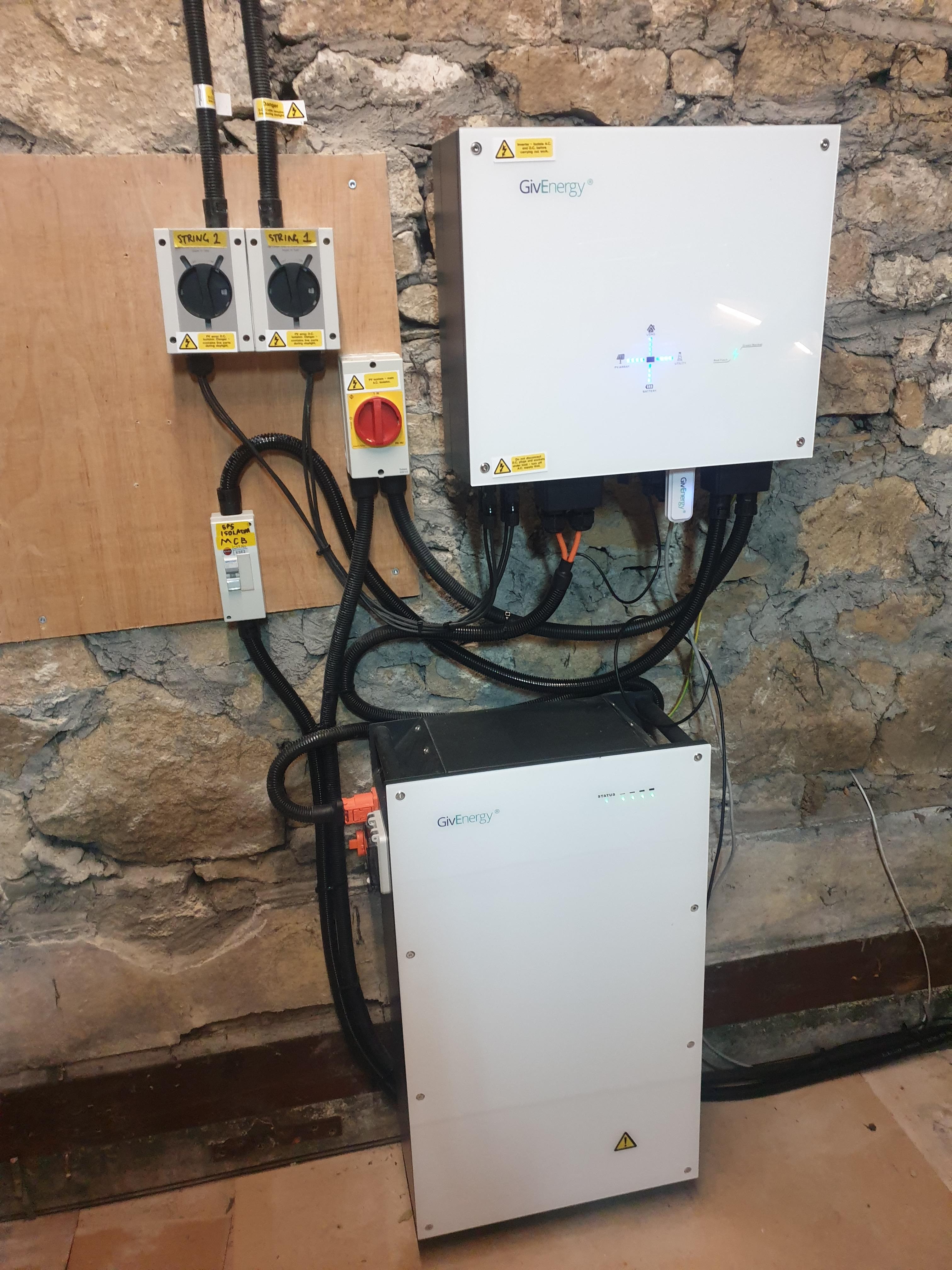
Wayland If you have a hybrid inverter then it can provide EPS power from the battery (and PV when available) but you need some additional wiring for it all to be usable. From your posts it sounds like this hasn't been done.
Looks like the EPS cables from the inverter are wired to that breaker on the left labelled "EPS Isolation MCB"
Where does the cable from the bottom of the breaker go? Looks like off-stage right somewhere...
rjp I think that was an example of what it would look like, not the original requestor's photo.
I have 2 consumer units.
One that is grid fed and that feeds the mains connection into the inverter.
The other is an Essential Consumer unit that has a number of outgoing ways- fridge socket, freezer socket, lounge power (tv and sky box), router socket and smoke detector heads.
This Essential CU is permanently fed from the EPS output on the inverter via the breaker you see which goes to a manual changeover switch such that in the event of inverter failure, I can take the inverter out of circuit and feed the Essential CU from the main CU.
TX200 D'oh.. 🙂

SteveCook
exactly what i am doing know. with a 25amp rcd at the eps output.
by far the most sensible way of using the EPS in my view. though more costly if you have to pay to have it done of course.
positor1 with a 25amp rcd at the eps output.
That’s fine for when you’ve got excess PV but if you have a grid disconnection at night, you’d want to ensure that your EPS load can’t exceed the output of the inverter on battery (2.5/3.6kW or 10/16A)?

My installer told me that GE told them for a gen2 3.6 the EPS current limit is 14A. And they fitted a fused 13A spur for my EPS which feeds the whole house with a manual switchover.
Maxwell A 13A fuse in a spur won’t blow at currents up to 20A according to this website:
https://www.pat-testing-training.net/articles/fuse-operation-characteristics.php
Best be careful to not accidentally overload your inverter.
Presume your have an RCBO on the output from your inverter as well as the fused spur?
Tim
You made me re read the requirements.
The ge information states "
The EPS output cable must be
protected as close as possible to the inverter with at least;
Double pole RCD protection at a maximum of 30mA
Overload protection between 6 – 25A
However point two's range is to cover the various inverters that they make.
For an ac3 with greater than 2.6kwh battery the rated output is 3kw so a 25amp rcd is too high.
at a voltage range of 230 to 250 the protection required is 12 to 13 amps.
I am unaware of a din rail mounted rcd that low.
With the 1.2 times rating of mcbs though a 10 amp one would allow 12 before tripping, not ideal.
I am leaning towards a 13amp rcbo in a single enclosure on the eps output under the inverter.
what have others done?
SteveCook Shouldn't the MCB in your photo be a two pole RCBO?
Well after numerous nuisance trips I have fitted individual RCBOs to each of the outgoing ways on my EPS consumer unit.
I dont know what goes on inside the inverter when and if it shuffles earths around but it would trip at random times every 2 or 3 days and nothing to do with rain and/or weather as everything is in bone dry loft.
SteveCook The Givenergy specs mention the EPS output should be protected by Double pole RCD protection at a maximum of 30mA.
Most RCBO's are single pole - are you 100% sure all the RCBO's in your EPS consumer unit are double pole?
From what I've read it's important for both the live and neutral to be disconnected in a fault condition when using the EPS.

EPS earth is not connected to the grid earth or the inverter casing at all. It is entirely separate hence the need for earthing provision by rod at all times.
hoggy I've had a question about this on Facebook as I'm going done the EPS route with manual changeover switch.
A earth pole with resistance under 200ohms is needed.
From what I understand according to the regs. in this link the earth pole is meant to be tied to the incoming earth:
https://electrical.theiet.org/wiring-matters/years/2021/84-march-2021/island-mode-earthing-arrangements-new-guidance-in-the-second-edition-of-the-iet-code-of-practice-on-electrical-energy-storage-systems/
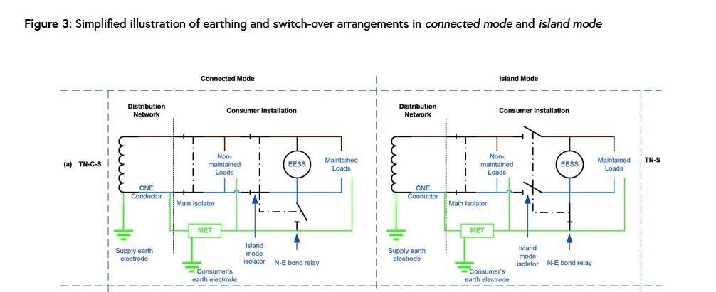
Edward Pass. But, as the installer put in what they say GE told them re EPS then if this breaks my inverter under some extreme use where someone forgets we are on pure battery or battery/solar then responsibility lies with them. And they did have to install the big 1.2m earth rod. I simpy asked for a capability they provided the solution.
Edward So yes pretty much that is how it's setup internally in the inverter with the relays creating the N-E bonding on EPS mode and so on.
The Givenergy KB does go into some depth in regards to converting EPS installations to TT however for reasons I can't be bothered to explain (because it takes too long) that's actually quite difficult to achieve in real life (particularly if it's in say an outbuilding or separate garage):
https://www.youtube.com/watch?v=S5OtLg6voZY
I had to get a massive rod (oooh Matron) to get mine down to a point where it was actually not useless, whilst also avoiding gas pipes, sewers, Morlocks and whatever else is down there AND still being on my land - but it is still connected to the main incoming earth as well.
(That too is technically not without risk - if you end up being the main earth point for the whole street in a fault, but that is very unlikely given the DNO will have stuffed in their own on a lot of the joints in the street already.)
Edward
2 pole RCD now fitted on inverter EPS output and main RCD in essential consumer unit.
Finding the stray neutral was a PITA but worth it!!
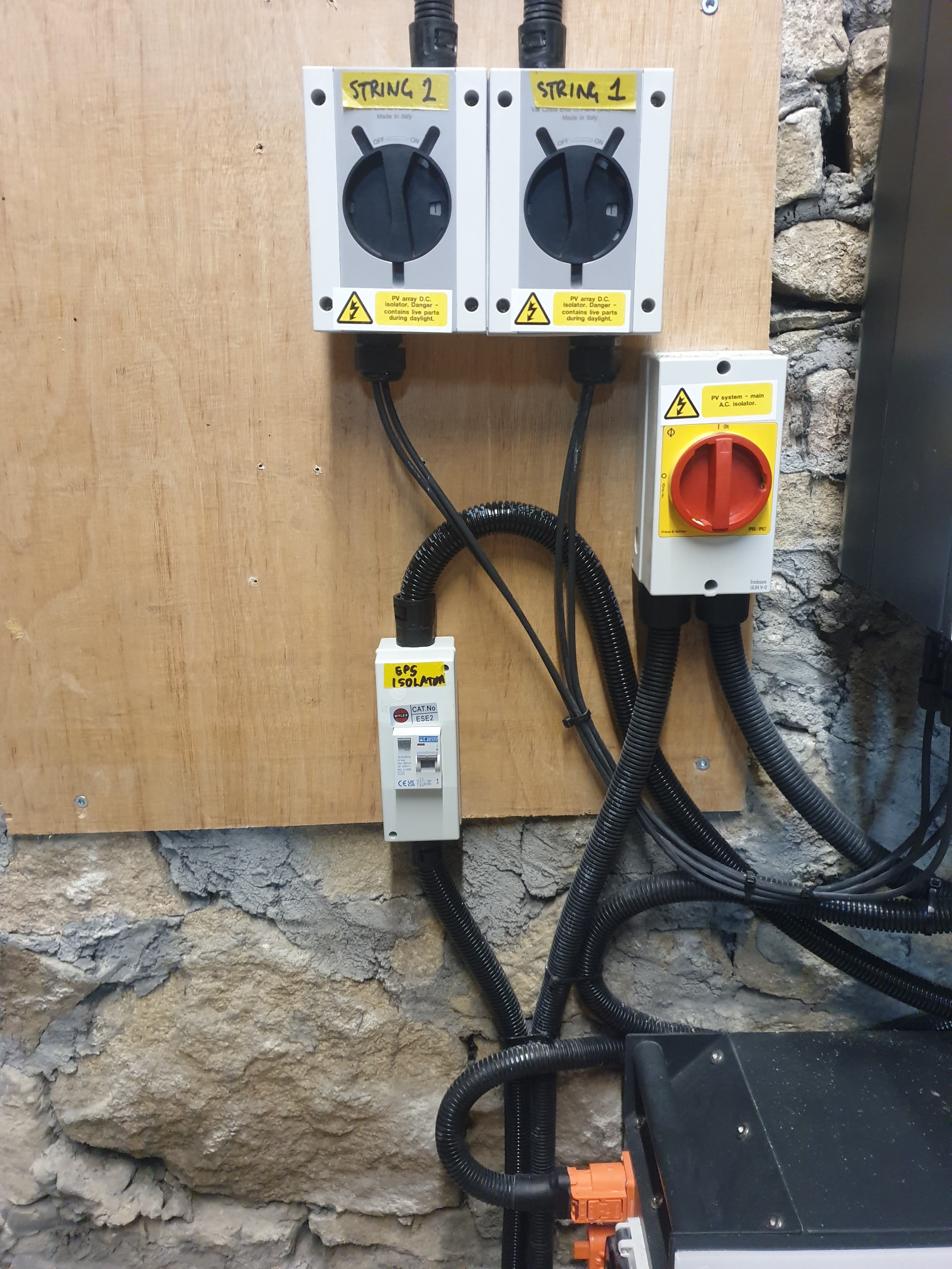
I have same inverter and battery as in the main picture and as I understand it there is potential to make a simple EPS - a pair of sockets next to the instal would do, or power to a ring main via the consumer board, which ever is simpler.
Does anyone know of an installer who could do this? Wiltshire.