
Battery Splitter?

15 comments started 2024-05-12 last 2024-06-22
GivEnergy ProductsBattery
P
#1 Pete.J

I wonder if an intelligent battery splitter would solve the multi battery problems that some users experience?
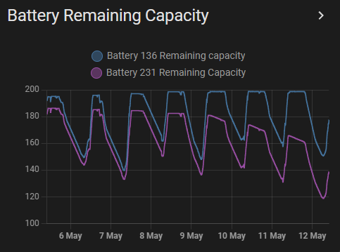
I had a PV system installed recently with a Hybrid 5kW Gen 3 and two 9.5kWh batteries, and after a few days of perfect operation I'm now tracking the secondary battery apparently losing capacity (see graph at end). There is clearly something not quite right here, but it did also get me thinking about how the two batteries work together.
As far as I can tell the inverter talks to the primary battery, which then controls the secondary. This could have the result that when the primary reaches full charge the inverter stops charging both batteries.
I wonder whether this could be solved by having a smart splitter box for multi-battery installations: the inverter connects to the splitter so it sees "one" battery as usual, and each battery connects to the splitter which acts as the "inverter" from the control point of view. The splitter would use the inverter data being sent to "the battery" to manage which actual battery to charge/discharge and by how much. Use the existing connectors etc and you would have a box that can be retrofitted if necessary and might help avoid some of the issues multi-battery users are seeing.

Anyway, here's the graph that prompted this thought. The big problem for me here is the second battery capacity apparently reducing while the batteries are under no load (and therefore shouldn't be discharging). I'm not sure a battery splitter would fix this, but I did think the idea worth sharing.
.

D
#2 DD

Pete.J Interesting... but seems to me that it's primarily a software problem, so adding another "intelligent" (I.e. software-based) component should not only not be necessary, but could add extra conflict.

#3 hoggy

Glossing over the fact that if you as a manufacturer support 5 batteries they should just work as opposed to coming up with intricate ways to fix something that shouldn't be in issue in the first place...
The batteries don't really talk to each other, just report back to inverter.
I fully belive that the issue is because they are daisy chained rather than in a ring like any other 'stack type' battery such as pylontech. So the further 'away' from the inverter they are introduces voltage drop each hop and so the later batteries see a lower voltage than the output terminals of the inverter.

In an ideal world all that needs to happen is for each pack to be a 'master' and so when each pack feels its at 100% it opens its internal mosfets (which these all have) and allows the rest to continue charging. This doesn't curre tly happen - 1 pack hits 100%' inverter sees this and simply stops charging.

P
#4 Pete.J

Yes, and it adds another point of failure. I don't know how much of the software required is already available in the inverter and bms code. It should however be an easy installation like a big "USB hub" for batteries...
I guess the question would be whether it was worth doing overall - is the risk worth the gain.

P
#5 Pete.J

@hoggy So effectively the system is a bit like an old coax network, and either a ring or a star configuration could be an improvement. If the issue is voltage drop as you get further from the inverter then a battery splitter would have each battery on the same length of cable so this should solve that?

#6 hoggy

I have a set of Pylontechs and a set of no name import packs and these are done in ring and star and hold within 1% of each other and have equal voltage applied. (Although equally the BMS is different to GE but I'd bet aside from that they would run much more instep)

P
#7 Pete UK

Pete.J

Is this what the upcoming CEMS will do?

Or will it just stop dual inverters cross charging leaving the individual multi batteries on an inverter still with a split in capacity problem?

  • there seems to be very little info out about what this CEMS will actually do. Surely it’s not a secret?

As the owner of 2x Gen 3 hybrid 5.0’s and 4x 9.5 batteries I’d like to know exactly how it will work. Rather than waiting years only to fit it and find out it only half solves the problems.

As @hoggy says, the problem seems to be the daisy chaining. And as you suggest, some sort of splitter (or power distribution controller) would, on the face of things, seem to be like a good solution.

The current “one is full = all are full” and “one is empty = all are empty” assumption based on an inaccurate SOC calculation/assumption doesn’t work well at all. If it doesn’t work properly from day one, what’s it going to be like after 5 or 10 years when for example one battery has lost more capacity than the other? You’re going to lose the same available capacity in all the chained batteries, with the inaccurate SOC indications compounding the problem.

#8 hoggy

CEMS in basic terms wrestles actual control of the inverter out from each inverter and puts it in a centralised box. So rather than each inverter doing what it feels is best (based on inputs from EM115 meters, battery & PV) they become puppets working under a supervisor (CEMS)

Now how far this stretches I don't know. Presumably the CEMS units CPU is much more powerful than a single inverter (otherwise you'd just make one original inverter CPU the master & not need the CEMS box in the first place) but just how deep intertwined it can get and whether it'll have the ability to knock batteries in/out of service I've no idea. I'm hoping there's a bit more to it than just something that could be done with Home Assistant and super fast data read/write (if you didn't care about burning through read/write cycles on the flash)

P
#9 Pete UK

hoggy

Yep. Me too

P
#10 Pete.J

I must admit I was thinking of something more like a network-style switch that would route energy demands or surplus from the inverter to the appropriate battery.

From the point of view of the inverter there is only one battery system, and each battery sees one device requesting or supplying power. The battery splitter would pass the lowest battery voltage to the inverter, and switch between batteries as required so a battery at 100% would stop charging, or current can be drawn from the battery with the highest capacity first.

GE could make one board and sell units that have 2 or 3 or 4 or 5 battery connectors on, so if you want to add another battery you simply buy another battery and a unit with more connections if you don't have any spare.

The thing that might be harder to work with is reporting the battery system capacity to the inverter: there would probably need to be some sort of software calculation depending on the number and type of battery connected, and then change the overall capacity stored in the inverter?

M
#11 mrand31

Note that Pete.J graph doesn't show the battery voltages. That would be interesting.

As an experiment, hows about:-
Shut the system down, Open the battery covers, re-set the DIP switches so that the furthest battery is now the master and the nearest one is the slave. Restart the system and see what happens to reported battery voltages and SOCs

P
#12 Pete.J

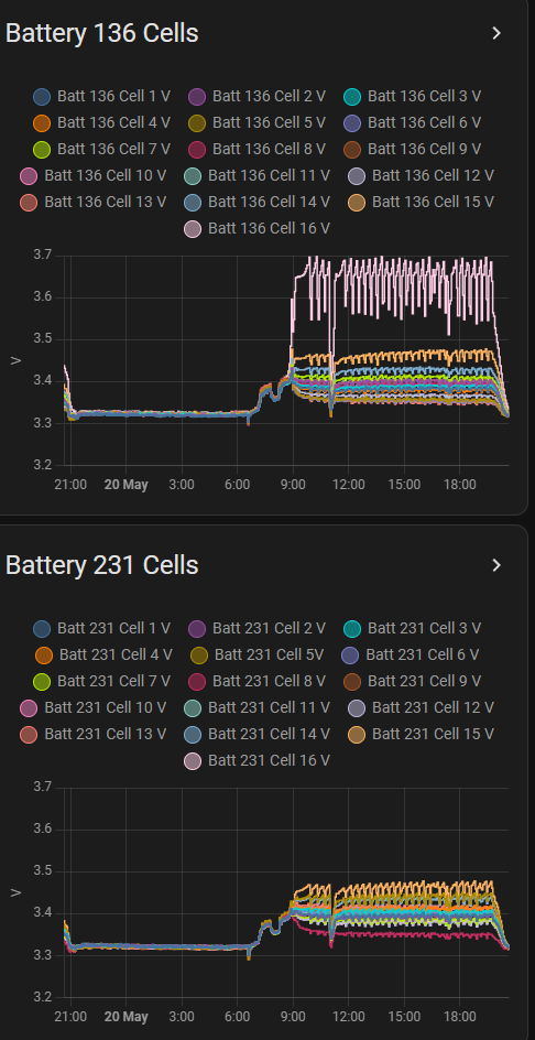
Voltage graphs as requested.
In my case, the primary battery has an "enthusiastic" cell 16 that reaches a much higher cell voltage under charging-no-load conditions. I believe this results in the primary reaching the overall target charging voltage while the secondary is still needs charging. The inverter stops charging, cell 16 is over-voltage and the primary battery triggers a small discharge (200W) to compensate and the voltage drops, eventually becoming low enough to charge (both batteries) again (slow charge at 50W) but cell 16 over-charges again and the cycle repeats.
I think the secondary loses effective capacity because it discharges with the primary but doesn't charge as "fast" and never has the discharged energy fully restored, which would explain why the remaining capacity (for the secondary) drops while under no load.
GivEnergy are aware of the problem and are organising a site visit to sort it.

If my system had a battery splitter that could route power for the batteries individually then the secondary and primary could charge independently and this issue would not show (although cell 16 would still be anomalous). My thinking was that a unit that saw the batteries individually but presented a single battery-system to the inverter would allow for different SOC values to be treated separately, which might mitigate some of the multi battery problems I saw people talking about.

P
#13 Pete UK

I think that’s probably what’s happening with mine as well. I’m seeing the same characteristic of the 200w continuous discharge on my first inverter pair. But I don’t have HA, so I can’t monitor the individual cell voltages. I’m seeing that 200w discharge all day basically on the first pair with all the solar at this time of year.

Meanwhile, now the secondary battery on my other inverter pair won’t discharge and is getting stuck at 100% (55v +).

Engineer is coming but we are struggling to get a convenient date. 🤦🏻‍♂️

Let us know how you get on.

P
#14 Pete UK

The way things are controlled at the moment, any mis-behaviour of a single cell in one battery messes up the whole operation of both paired batteries.

I do sincerely hope the CEMS fixes this.

P
#15 Pete.J

Update: the engineer arrived promptly and was very helpful - we had a good chat and I learned a lot. He changed the Battery Management System board for my errant battery, and moved it to be the secondary battery. The batteries have now settled with a 6% SOC difference (secondary being lower) and the overvoltage cells are behaving themselves at the moment. I'm seeing small fluctuations, but nothing like the problems I had before the BMS change.
Since the secondary battery seems to always be lower SOC in the pair, I'm even more convinced that an active battery splitter would be a good idea: it would be able to cope if one battery fails or has to be turned off, and it would enable each battery to reach full charge. Potentially, with some coding, it could give the ability to calibrate a single battery in a multi-battery system...