AIO and GW wiring question

13 comments started 2024-12-11 last 2025-05-10
CommisioningGivEnergy ProductsAC CoupledBattery
W
#1 Weasel

Hi

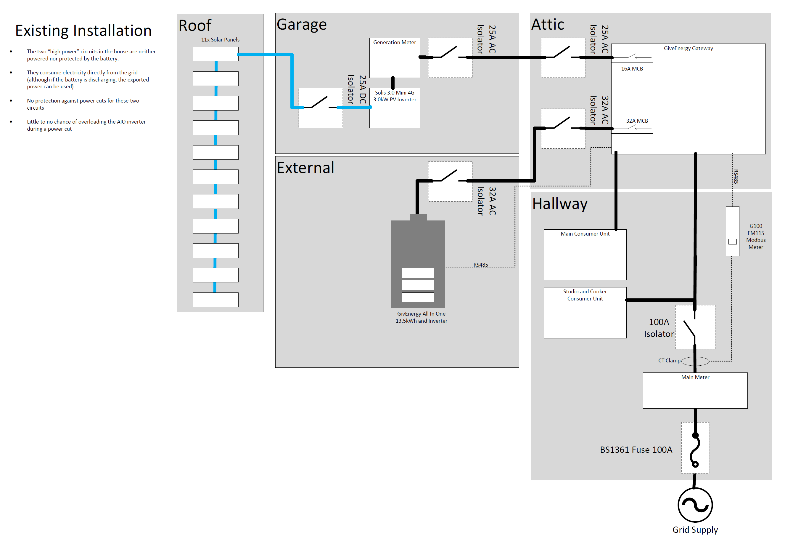
I had my AIO and GW installed about 6 months ago and as part of the design, I deliberately asked for 2 circuits to be left unprotected by the battery. These circuits are for my cooker and my wife's studio and both of these could together potentially overwhelm the 6kW limit of the AIO during a power cut. My thinking was that these circuits are potentially high-load, but I can live without them during a power cut.

FYI: I am with Octopus Energy on their Cosy tariff.

The diagram below shows what I have now and it works well for me other than I am paying the prevailing rate for cooking and for the heat pump in the studio. I am able to mitigate the latter by running the heat pump during my Cosy periods wherever possible, but my overall electricity import cost is about 7-10% higher than if everything were connected to the battery.
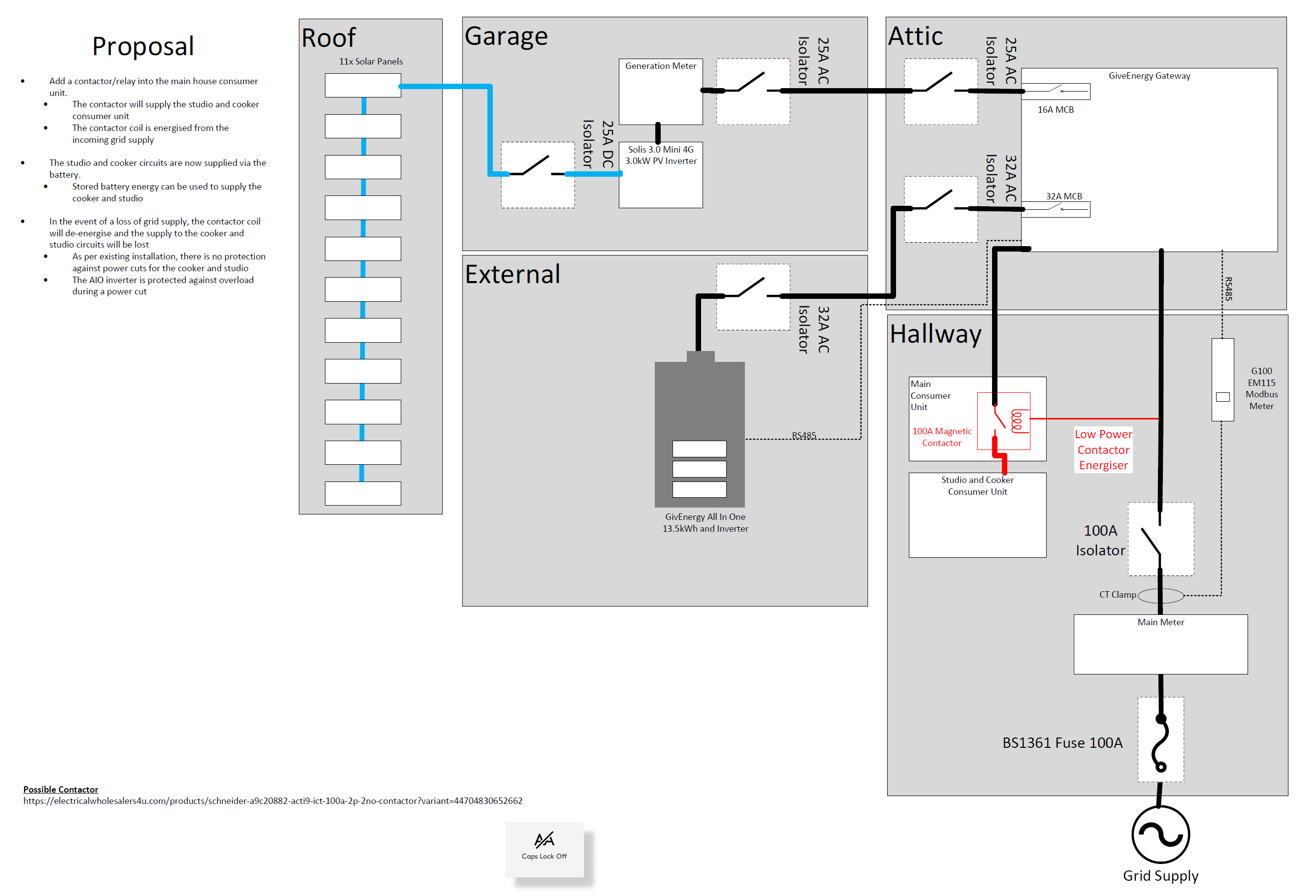
Re-examining my rationale for isolating the 2 potentially high-load circuits, I realised that if I could have them running on the AIO/GW in normal circumstances but isolated/deenergised during a power cut, I could have the best of both worlds. With this in mind, I drew up the following suggested wiring diagram that adds in a contactor (relay) that has normally open contacts. The proposed diagram is below
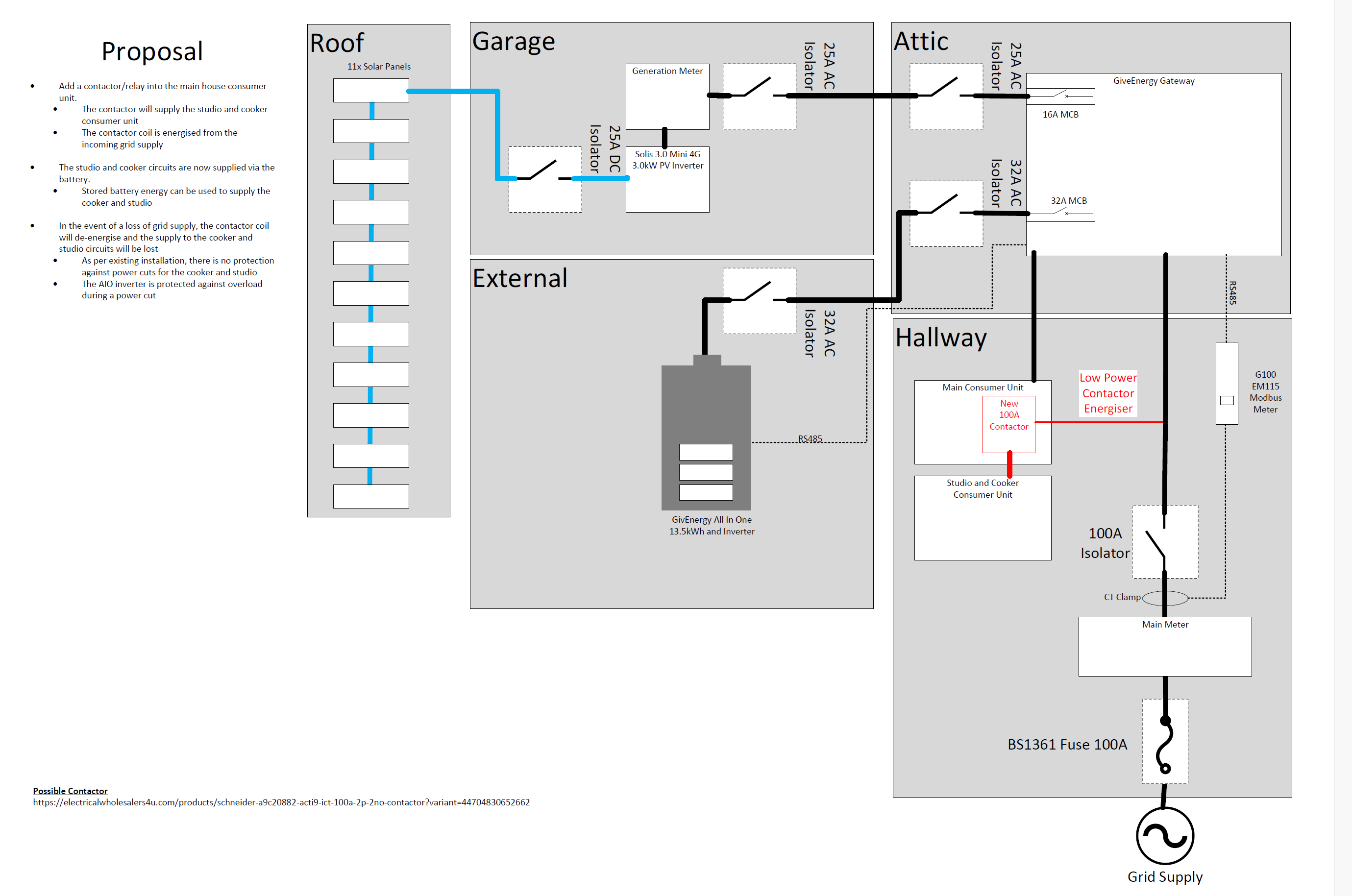
During normal operations, the contactor control circuit closes the contacts, thus connecting the potentially high-load circuits are connected to the AIO and will draw power from it. If the overall required power exceeds the battery capability, then excess will come from the grid

In the event of a power cut, the 2 circuits would be deenergised - exactly as they are now, but the difference is that once power is restored, they are reconnected to the AIO

I suggested this to my installer who asked my to pass it by GivEnergy which I did. The response from GivEnergy was:

This isn't really something we can advise on. You would need to confirm with your installers whether or not this is something they are able to complete. The only worry I have as you are splitting your load with a contactor that it may cause issues with the change over time and when the grid comes back. Your contactor may see (depending on how it works) the grid reinstated but the AIO and GW are going through their realignment process which may cause issues. I have not heard or seen an installation of this type previously.

I have asked GivEnergy for a more detailed explanation of what issues might arise and am awaiting their response, but without an endorsement from GivEnergy, my installer is unwilling to quote for the work to be done fearing potential warranty issues if this idea is "not approved".

Meanwhile can I ask the knowledgeable folk on here whether they think think that my proposal is feasible, sensible, practical and safe.

Thanks In advance
Chris

#2 hoggy

Weasel you'll blow your AIO up with lack of grid sync using the contactor for bridging. As they say, it'll reconnect the grid to the island mode side of the gateway before the gateway has resync lock with the grid (currently you'll note the changeover back to on grid is not as instant as going in to island mode on loss of grid)

W
#3 Weasel

hoggy Thanks for the reply, but am I misunderstanding what a contactor is? I understood that it is just a large relay and that the control circuit is totally separate from the load circuit.

In my mind, there is a low power feed from the grid to the coil of the contactor which then switches the load circuit.
Therefore there will be no bridging between the grid side and the AIO side.

Am I wrong about how a contactor works?

W
#4 Weasel

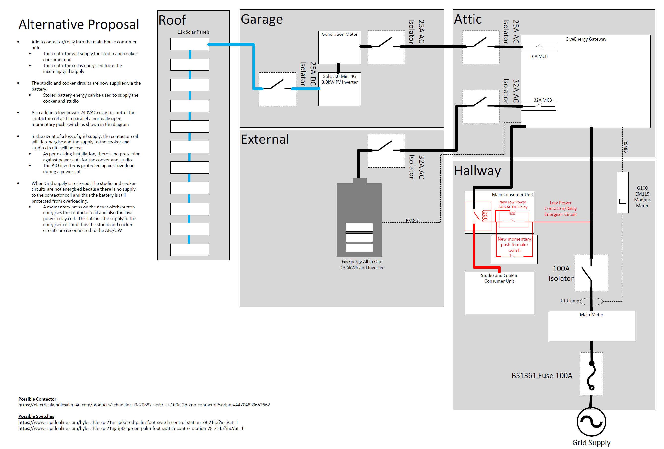
For clarity, I have re-drawn my proposal shown that the grid supply is always isolated from the battery protected circuits

#5 hoggy

Weasel apologies, hadn't scrolled right enough to see your layout drawing. So your using the contactor solely to drop out the supply solely now fed from the gateway, rather than to feed from grid or gateway depending on grid state. That should in theory work OK.
I'd add a timer to the contactor such that when grid comes back it waits for X min for the gateway to resync to grid - otherwise you may overload the AIO if it hasn't yet got itself connected back to grid by the time the contactor throws over.

All is perhaps moot however as I doubt you'll get Giv to endorse or OK it, without which I suspect your installer will not like to take on the risk, as they'd be on the hook should anything go awry (it allows Giv an easy warranty 'out' if they don't say either way its acceptable)

W
#6 Weasel

hoggy That's right hoggy, I am only using the contactor to drop out the supply when the grid drops and not to switch from grid to AIO and back.

Thanks for the suggestion of a timer, I have an alternative idea that would require pushing a "mushroom" to reconnect the secondary consumer unit. I will sketch it out and post it later

#8 hoggy

Weasel OK, you might need to pick up some aux contacts depending on which contactor you go with to hold the coil in. Over complicating it further you could have a key switch also fed from gateway as well as grid, so you could pull the contactor in from gateway power if you really needed to use it in an emergency (and kept everything <aio capacity)

W
#9 Weasel

Here is my alternative which when the grid supply is established, now requires a momentary press on the new switch/button in order to establish supply to the secondary consumer unit

The use of the low power relay connected as it is means that a momentary press of the switch/button will latch the relay in the on position until the grid supply is lost. When the grid supply is lost, power to the secondary consumer unit is lost until grid supply is restored and the button/switch is pressed to latch the low-power relay

W
#10 Weasel

hoggy

I cannot see circumstances that require me to power the the secondary consumer unit in the event of grid failure and your suggestion of a key-switch might potentially bridge between the AIO side and grid side, but thanks for the thought.

W
#11 Weasel

My installer will be visiting me in the new year to check the positioning of the wiring etc with a view to implementing the wiring as per the latest diagram above

D
#12 Daveb01

Weasel

I don’t see an earthing rod and where you are connecting it? This is a mandatory requirement with a system that has power backup.

W
#13 Weasel

Daveb01 everything is earthed. My installer added an earthing rod at the gateway when the system was originally commissioned 6 months ago. The diagram is simplified for clarity and the only changes are those in red.

W
#14 Weasel

Just to wrap this one up.

I eventually went for a solution based upon a time-delay relay instead of a push-button in order to restore power to the studio and cooker. When grid power is restored, the relay waits a minute or two before energising the contactor coil and thus re-energising the studio and cooker circuits.

The electrician was on-site yesterday and did the necessary rewiring which was a bit more involved that I had first thought because every single circuit needed an isolator switch, including the relay control. This meant I needed to swap out a small secondary consumer unit for a larger one in order to fit the required bits and bobs.

It wasn't a cheap solution because the 100A contactor cost £lots, but I was aware of all the required changes and costs up-front so I know what my payback period looks like

TL;DR My studio and cooker circuits now run off the AIO/GW but are disconnected in the event of a power cut. They get reconnected a minute or two after the grid is restored; this allows time for the AIO to sync to the grid @50Hz before trying to add a potentially heavy load.