Fooling a CT clamp

26 comments started 2025-02-25 last 2025-03-01
GivEnergy ProductsAC Coupled
6
#1 666tim666

I have an AC3 inverter and 9.5kWh battery. I use an Octopus Economy 7 tariff to charge it over 7 hours at night and I run the house load from it during the day using the 'eco' option. The tariff unit costs are 12.45p at night and 29.72p during the day and evening. So nothing challenging about that.

I have recently fitted an 'Octopus Home Mini' and I can see my live power use as being maesured by my Smart meter. It shows that I have a continuous import load of 5 or 7 watts during the day. Now that's not right because the GivEnergy App shows zero grid power flow. That 5 or 7 watts is costing me 6p or 8p/day or £25/year and I object to that. But how to stop it? Note also that I am on or will shortly be on an export tariff of 15p/unit and so unplanned export power is not wasted - it's erroneous import power that is the problem.

If the givEnergy inverter had a parameter to tune the behaviour of the power metering on the grid input then that would be excellent. But it doesn't.

However, passing a small AC current, eg 50mA, through an extra, thin wire through the GivEnergy CT clamp on the live house input from the smart meter causes a metering adjustment, either positive or negative depending on the phase, which alters the behaviour of the inverter. By causing the inverter to think that it is sending 7 watts more to the grid than it actually is, an extra 7 watts is produced, and that reduces the actual power draw through the smart meter to zero.

I have done this using the 16volt AC output of train set transformer and a suitable resistor, and it works. So now I am building a small AC power supply (6V 2.3VA transformer). When fitted it might consume 1/2 watt as I only need a very small power flow.

Different installations may well have no metering error or may have a larger one, or the error could be export and not import. I don't know whether other people see this, or whether the cost is too small for them to worry about. But I prefer my Home Mini to show zero power flow.

Does anyone have an alternative approach?

#2 Windy Miller

666tim666 That's pretty clever.

It's the phase of the AC that must be right so that it enhances or diminishes the clamp reading depending what you want. Once you've built your 6v transformer, if it doesn't quite do what you want, pass the thin wire the other direction through the clamp.

You can use this thin wire not just to zero the grid current but to bias it positively to a small export if your house battery doesn't go flat too quickly.

Most people aren't too worried about this small grid input and you'll never be able to fully zero it out as when a house load shifts current the inverter takes a small amount to time to respond and during that second or two the extra comes from the grid.

If it takes 2 seconds to respond to your 2KW kettle coming on that is equivalent to 15 minutes of your background load.

6
#3 666tim666

Windy Miller Thank you for your comments.

Yes, the grid import and export does fly up and down when the inverter is adjusting to a load change or solar panel output. I will find out just exactly what the benefit will be only when I try it in practice for a period. The power supply I am building will have two sets of screw terminals to: 1 connect the wire - so that it can be threaded and/or reversed and: 2 to fit an additional resistor in order to allow for adjustment of the current flow. The supply will have an internal 20 ohm to make the max current 300mA.

I have looked for a commercial 'plug top' PSUs with an AC output but they all seems to be 12 or 24v at 1 amp or more.

#4 Windy Miller

666tim666 One thing I have noticed in the forum is some people cannot zero out their inverter and the background load is sometimes hundreds of watts. In these cases there must be a fault somewhere in the system. I usually ask people to check that their clamps are tight shut and are around the right cable. But I can believe that some clamps just mis-read (or some inverters convert what they're seeing incorrectly). If the clamp signal goes through some signal conditioning circuitry a poor design or component fault could easily put a DC bias on the signal before it is converted to digits.

D
#5 DD

666tim666 good idea. You could presumably pass the wire through several times, to amplify the effect of an even smaller current?

6
#6 666tim666

DD Now I didn't think of that - it's a good idea. And, of course, it's a way of having more effect while using less current which reduces power used.

#7 Windy Miller

You can do all sorts of clever things like this. If the AC 6v follows the grid voltage (which if it's a transformer probably will) then so will the offset. Or if it follows some other appliance you could alter the offset depending on say the amount of solar. Not sure why these might be helpful though.

You could fool the inverter into charging or discharging the battery independent of any settings (or DNO limits for that matter).

6
#8 666tim666

Windy Miller I think an error of the magnitude of hundreds of watts would put it into the category of a faulty installation which needs to be repaired or replaced.

A significant error could occur if an installer has made the mistake of shortening the wires from the current clamp to the meter. And if the digital communication between the meter and the inverter is unreliable for some reason then that obviously would cause problems.

I keep monthly records of the readings on my smart meter and also on the display on the GivEnergy clamp meter. I am intending to put an analysis on here when I have sorted it out. Generally speaking it shows what I would suspect which is that at low power usage the clamp suffers a larger error than at high power usage. However, the error displayed is, consistently, that all of the clamp monthly readings understate those from the smart meter.

6
#9 666tim666

Windy Miller Yes, I think you could actively manage the behaviour of the inverter by altering the flow through the clamp. But I think it would just defeat the inverter management parameters and complicate things. As you say, it doesn't seem helpful.

#10 Windy Miller

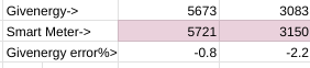
666tim666 My records over a whole year show a -2.2% error on exports and -0.8% error on imports which is pretty good actually.

R
#11 Rubikcube

[unknown] If the givEnergy inverter had a parameter to tune the behaviour of the power metering on the grid input then that would be excellent. But it doesn't.

Are you sure it doesn't? Register 104 is described as "Grid Power Adjust". It's set to zero on my inverter.

I haven't tried adjusting it, so no idea if it does what you want.

6
#12 666tim666

Rubikcube I cannot find a "Register 104" or something calling itself "Grid Power Adjust" on my system, either on the GE website login, on Home Assistant or on the GE mobile App. So maybe my inverter is too old. Its an AC Gen1. Is there somewhere else that I should look for this setting?

Thanks for the idea. Tim

R
#13 Rubikcube

[unknown] Your AC3 is controlled by 180 registers (numbered from 0 to 179). GE kindly allow you to manipulate just 17 of them via their app or the portal. The other 163 are hidden from you (and aren't available in home assistant either).

My guess is the original designer thought that the setting might be useful, but GE block it from user access so they don't get support calls from people asking "What does grid power adjust do?".

If you want to access it you will need to do some programming (python, java, kotlin, bbc basic) and accept that if things go wrong, support might not help you.

#14 hoggy

Rubikcube doesn't seem to want to set for me (via Givenergy_modbus) - just throws a "Function Code 86" error. (Which either points to it being an AC3 only register or that error catch doesn't necessarily mean what it says)

D
#15 DD

hoggy The top bit of the function code is just the error bit. Not sure why 134 / 0x86 has been singled out as an AC-specific code - it's just WriteHoldingRegister (6) with the error bit (128) set ?

6
#16 666tim666

DD Oh? So is that a 'it's possible but we are not sure' question? Thank you for trying.

I was good at Usercode Assembler language for ICL System4 but that was a while ago (like 50 years ago). I can just about tolerate python, but object-oriented languages seem so inprecise. YAML is awful.

Tim

#17 hoggy

DD only mention it gets is a cryptic:
The critical message is not an error and can be ignored. It’s tracking a fw bug in the inverters which GE are aware of
Over on github
What the actual bug is or means I've no idea. Maybe there's some registers that are off limits even to modbus changes?

R
#18 Rubikcube

[unknown] You are correct.

Tried setting register 104 to 1,2, 3, and 20. All rejected.

No idea what it might accept nor what it does, so best left alone.

R
#19 Rubikcube

hoggy You are correct.

Tried setting register 104 to 1,2, 3, and 20. All rejected.

No idea what it might accept nor what it does, so best left alone.

#20 TheDragon (GivEnergy)

Setting engineer registers will very much void your warranty. External changes to ANY register are logged at the portal.
A support claim will have access to these.
There is a good reason a lot of the registers are not made available.

Be very careful, especially discussing on an open forum

#21 hoggy

Warranty is the least of this inverters concerns! (But yes for more "normal" users I'd expect nothing less warranty wise)

K
#22 KevinB

TheDragon (GivEnergy) how does that stance work when there's no authentication on the TCP modbus interface? Any software on any computer running on the local network can send a packet, not needing any auth or shared secret, and then void the warranty without the owner knowing - how would you show that the owner did it knowingly?

Too make it worse, the wifi dongle's AP can't be disabled, and is often left on the default password, so it can even be done from outside of the local network.

I understand and agree with your intent on the "that would void the warranty" message, but I think it would only make practical sense if:

  • that was documented somewhere
  • there was even a rudimentary effort to prevent instructions that the owner didn't authorise, either from on or off the local network
  • the firmware on the device made some effort to reject harmful changes, surely it's a bug that it can be made to damage itself
6
#23 666tim666

[unknown] Have finished the AC power supply and fitted it. I have looped the wire once as suggested by "DD", thanks. I think the current is about 40mA but I don't have an AC current multimeter yet (it's ordered). The correction is a bit high as I am reading export of 10 or 20 watts on the Octopus Home Mini most of the time, but as I am now paid for export I am not concerned.

I have taken pictures but I don't know how to put the jpg files in here. I tried drag and drop but the page said 'oops something went wrong'. Maybe there is a size limit.

The AC supply has provision for fitting (and changing) an externally mounted resistor in order to adjust the current.

Tim

6
#24 666tim666

Windy Miller Have finished the AC power supply and fitted it. I have looped the wire once as suggested by "DD", thanks. I think the current is about 40mA but I don't have an AC current multimeter yet (it's ordered). The correction is a bit high as I am reading export of 10 or 20 watts on the Octopus Home Mini most of the time, but as I am now paid for export I am not concerned.

I have taken pictures but I don't know how to put the jpg files in here. I tried drag and drop but the page said 'oops something went wrong'. Maybe there is a size limit.

The AC supply has provision for fitting (and changing) an externally mounted resistor in order to adjust the current.

Tim

#25 Windy Miller

666tim666 Try cut and paste for the pictures although I think you are probably just hitting a flaky forum since GE updated it a couple of months ago. Keep trying and if necessary try to edit in your pictures by editing your own post if you can't get it through in one go.

An export of 20W will be less than half a unit in a day which isn't too much of your battery. You may still see small imports though as the inverter takes a couple of seconds to match the load.

By doing the adjustment this way (no fiddling with registers) your warranty will be unaffected. Your stats may be a little bit off as the energy registered from your small wire isn't real of course.

6
#26 666tim666

Windy Miller OK, I will try the pictures again.

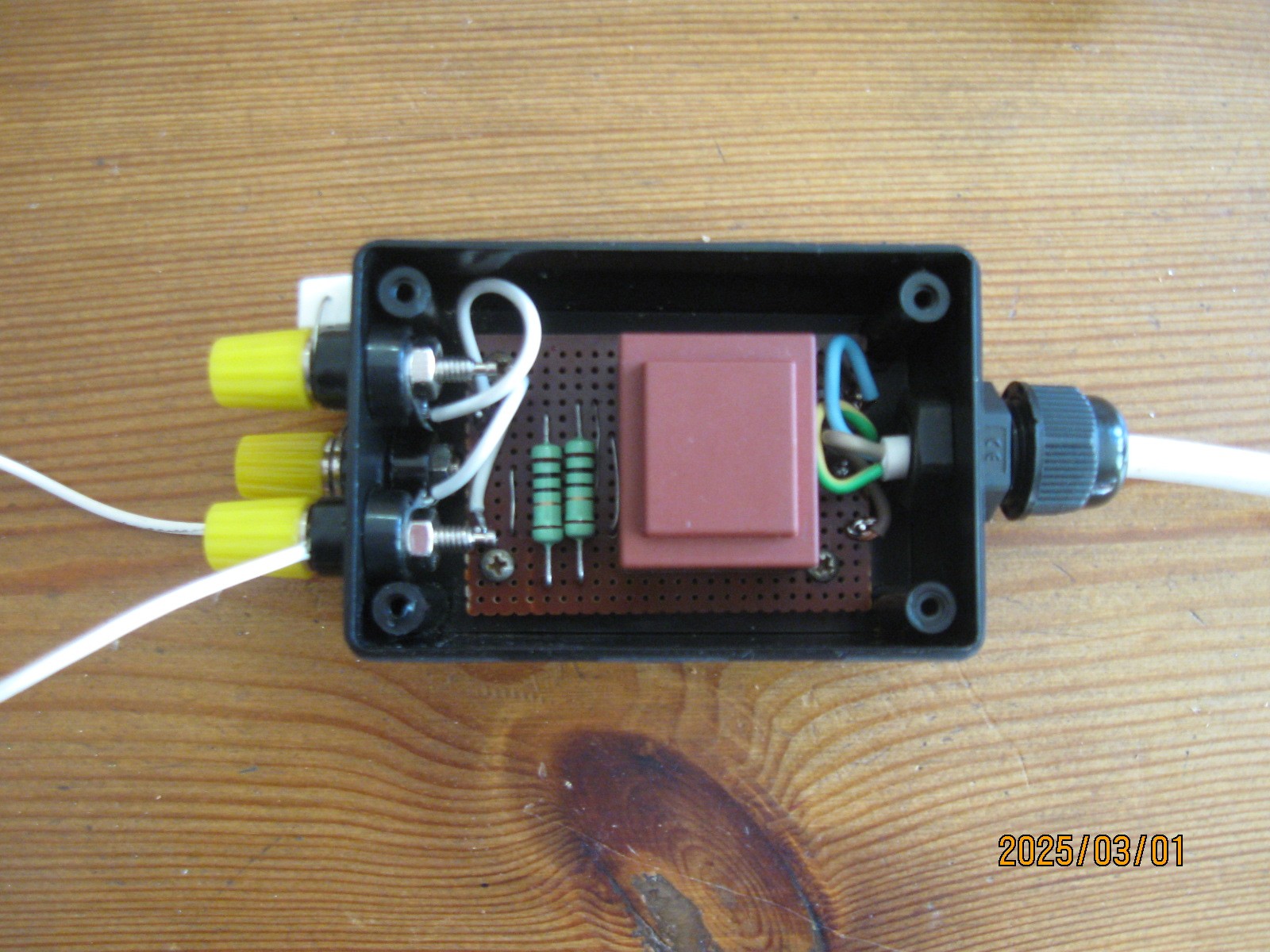
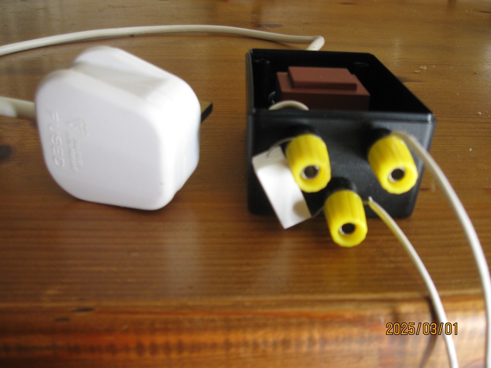
The first picture shows the build. The second picture shows the output terminals. Note that the bottom one is not connected internally - it is just there to allow for the addition of a series resistor to control the current.

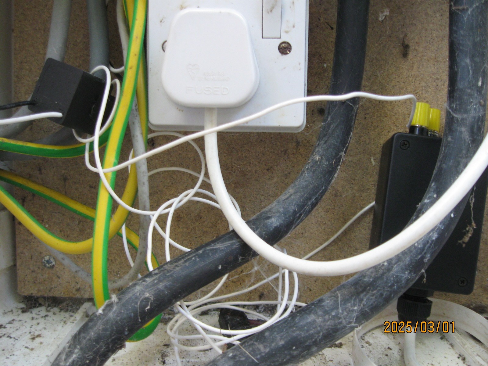
The third picture shows the device in situ with the loop running throught the clamp.

I am now using a 300ohm resistor and the current flow is 33mA. There are two loops through the clamp so that effect is doubled to 66mA. 66mA is equivalent at 240volts to a bias of 15.84watts.

Tim