Cell voltage over 3.65 volts

21 comments started 2025-05-12 last 2025-06-12
GivEnergy ProductsBattery
R
#1 Rubikcube

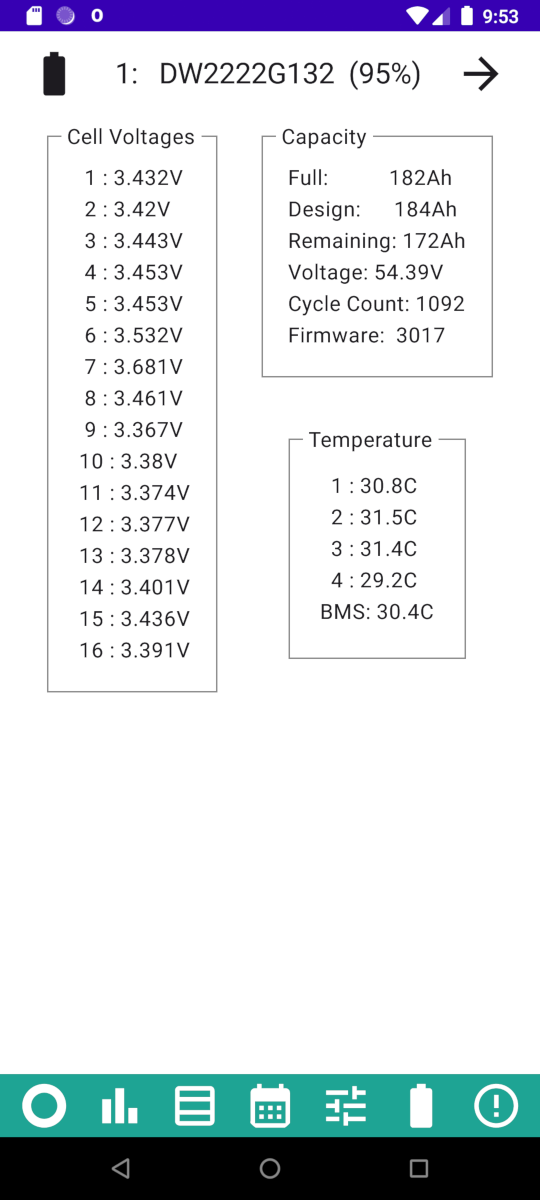
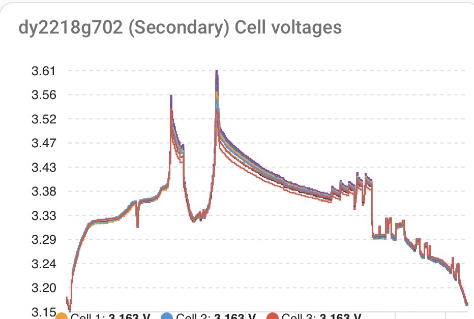
Noticed this morning that one cell (number 7) had managed to reach 3.68V. This was shortly after a BMS overvoltage fault.

All the tables I have found suggest 3.65V as the maximum recommended for LFP.

Do GivTCP users see this in the cell history? Should I add cell voltage history monitoring to my app? Would upgrading the BMS firmware to 3020 make any difference?

V
#2 Vestas

Rubikcube On BMS f/w 3015 I've seen a cell (cell 3) at 3.7V for 20-30 minutes using GivTCP which prompted me to run some automations to prevent it. The portal didn't report it as an issue.....

As to whether to update f/w - well for me its the devil you know etc. I understand how 3015 works with this inverters "fast response" f/w so I know when its lost the plot on SoC simply by glancing at cell voltages and SoC.

If you did implement voltage history then you should probably have a "top ten voltages" list which would make it easier to work out if there's a recurring issue.

Edit - looks to me like you're about 800-1200Wh out on SoC vs reality. Let it go to minimum SoC and leave it there, I bet it finds a kWh over the course of a couple of hours. Lots of PV charge always has this effect IME....

#3 hoggy

I'd be a little wary of 3020 given my experience. It may just be its not set up with 80% DOD in mind of my old pack but it has potentially reduced capacity a fair chunk (which seeing as nobody else has noticed may well be the case that I'm an outlier)

I have been playing with just top balancing today (sending "3" to the calibration register) and it spent nearly 2 hours finding the true full value again. Whether this is enough to correct my woes we shall see (it didn't spend anywhere near that long doing the same on the last full calibration run last week)

The bms should fault at 3.65V but there is a delay timer so it can creep past it before the inverter notices. (That and I'm not sure how often the inverter polls the bms anyway, don't think it's that often to be fair)

R
#4 Rubikcube

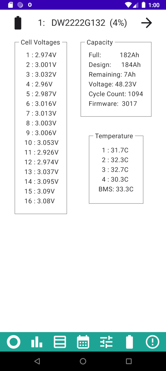
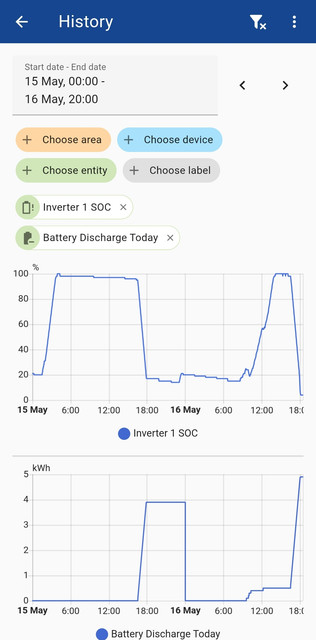
Thank you for your input. When the battery has been "fully charged" previously, the voltages have been much closer. I wouldn't be concerned about 1 cell at 3.65V if the others were 3.5V (ish) and above. When the battery discharged (to 4%) the voltages all looked fine.

I think I have been a bit complacent about monitoring the cells. For the first two years the battery has performed brilliantly. I now sense that it may not be quite as good as it once was.

Sticking with 3017 for now (because it's still working well). No point calibrating until I have good monitoring in place. Working on adding cell monitoring to my app.

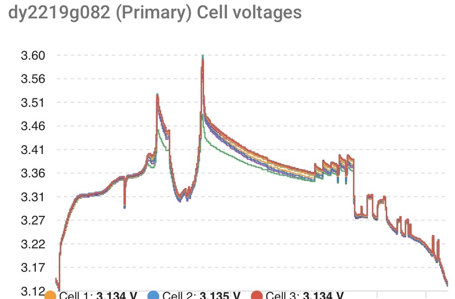
For reference this was the state about 15 hours later when the battery was "empty". Intriguing that the cycle count has gone up by 2 for only a discharge.

G
#5 geoffreycoan

hoggy I'd be a little wary of 3020 given my experience. It may just be its not set up with 80% DOD in mind of my old pack but it has potentially reduced capacity a fair chunk (which seeing as nobody else has noticed may well be the case that I'm an outlier)

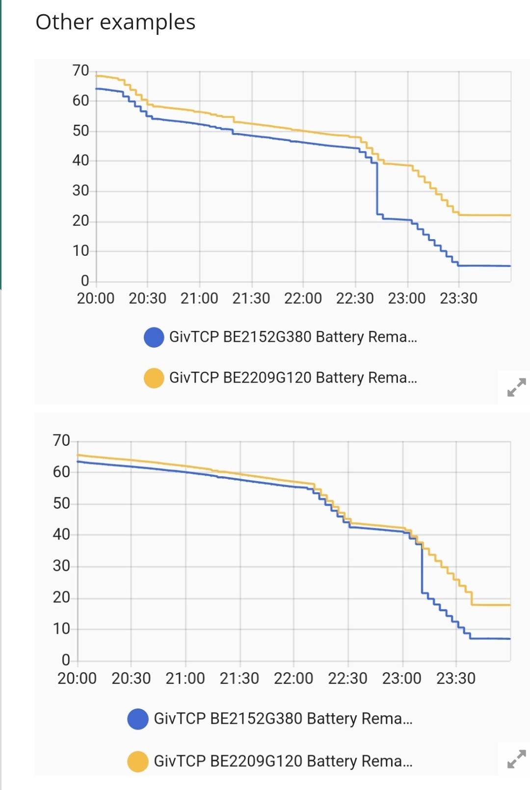
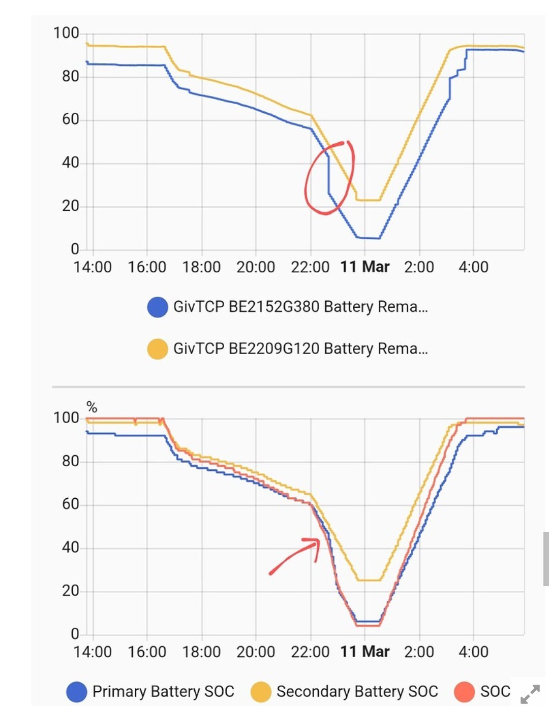
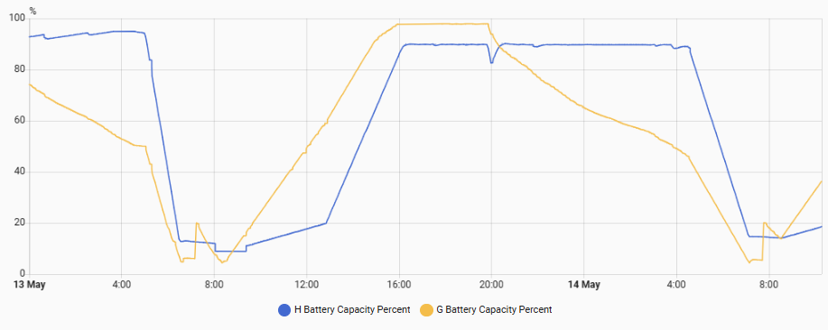
Its not just you. I upgraded my 5.2 battery (H, blue line) to 3020 yesterday morning and have noticed that the battery remaining capacity has reduced from a peak of 96.85 to 91.5 which reduces the battery capacity (percentage of design capacity) from 95% to 90%

I was giving it a day or so to see if it recovers on its own, but so far it hasn't despite a full cycle, and then I plan to do a recalibration to see if that resolves it.

The orange line is my 9.5 battery which is still on BMS 3015. Weird little jump of battery remaining capacity from 11% to 34% that has happened both yesterday and this morning. Its when the batteries are being fully discharged ready for a trickle solar charge. Must be an artefact of the battery SoC tracking rebalancing itself.

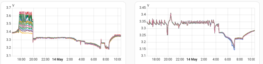
Looking at the cell voltages @Rubikcube I see spikes up to 3.651V on cell 13 and slightly lower on cell 5 of my 9.5 (left graph), but nothing like that on the 5.2 (right). The 9.5 is I think overdue for a recalibration so BMS 3020 on the 5.2 was my first step towards moving to the latest firmware and doing recalibrations on both

Interesting that during all that cell voltage bobbling along last night on the 9.5, the SoC remained constant at 100%

R
#6 Rubikcube

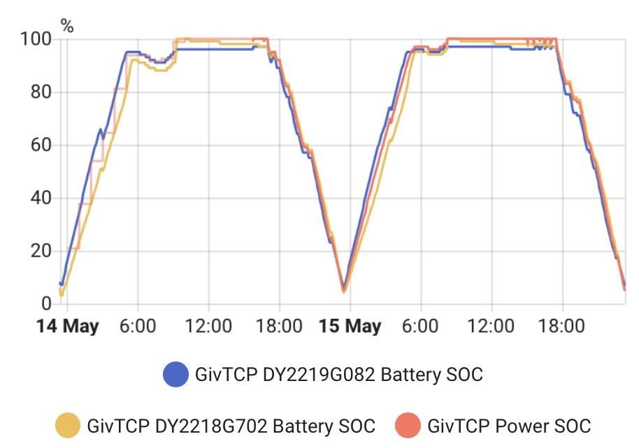
geoffreycoan I think if I ran HA, I would get a very similar graph to yours for my 9.5.

My plan, rather than gathering lots of data in a database, is to monitor the cells through the day, and just record the max (and min) value for each cell on a daily basis to a log file. Then I can analyse that over time. Hopefully I will have some results next year!

I have seen others mention the tendency for 3020 to stick at 100%. Think I will be sticking with 3017 for the time being.

G
#7 geoffreycoan

geoffreycoan @hoggy further to my post above about loosing available capacity on my 80% DoD 5.2kWh battery,

Prior to the upgrade on BMS 3015 when the battery was reporting 100% SoC, the battery remaining capacity was reporting around 96.85kWh vs 102kWh design capacity - in of itself a 5.1% capacity loss (after 1300 cycles).

After upgrading to BMS 3020 the battery is now reporting 100% SoC as being at around 91.6kWh remaining capacity, i.e. a further 5% loss of capacity.

I did a slow rate recalibration this morning to see if this cured it, but it didn’t, available capacity now being reported as 92.3kWh at 100% SoC, which is a slight improvement but still loss on BMS 3015.

Have reported this to GivEnergy

M
#8 mpartington

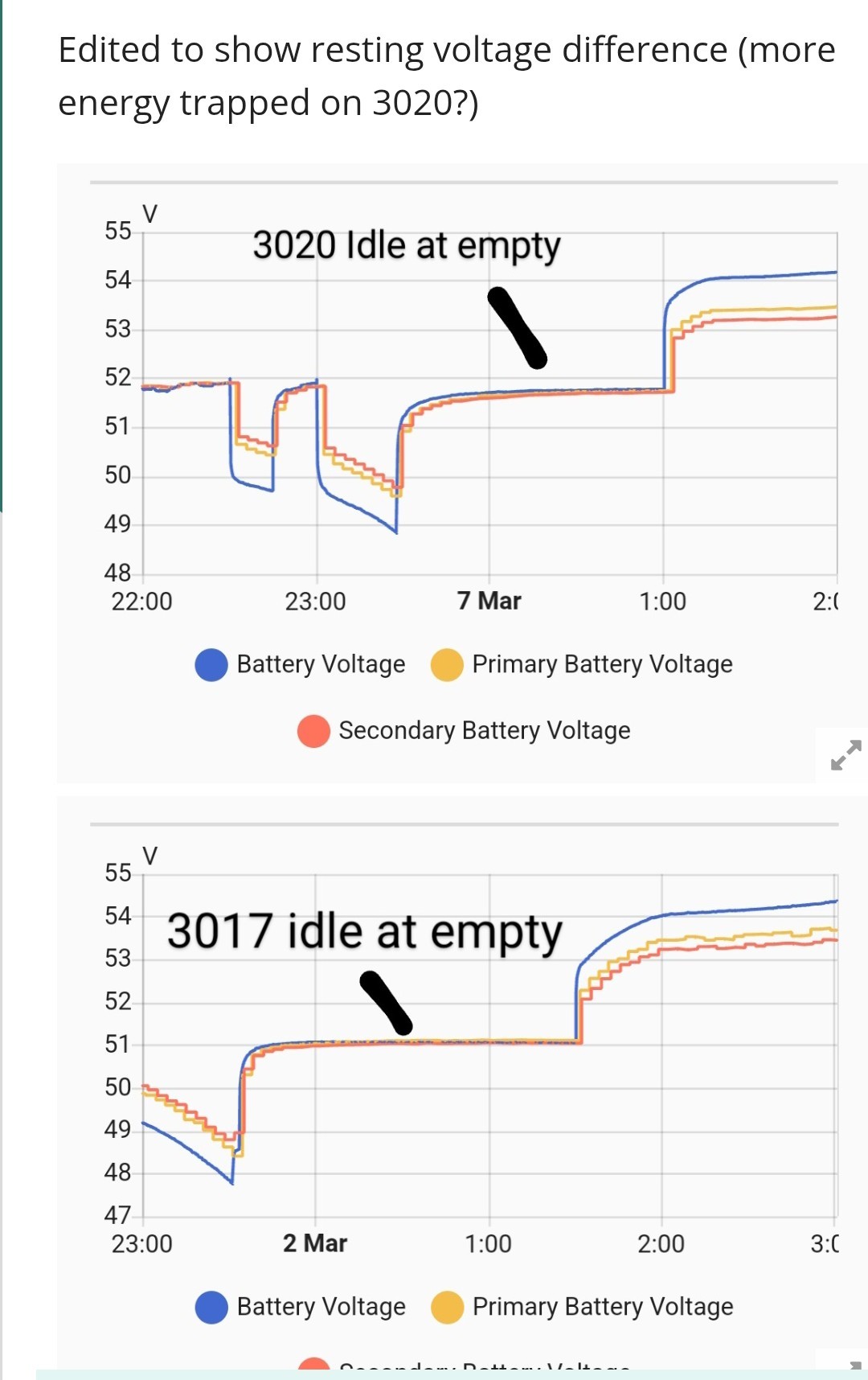
+1 on reduced capacity. I have 2x 5.2kWh batteries on an AC3. I first reported this over in the beta forum a couple of months ago, but no one else had any issues and I think I was seen as an outlier, so no real investigation (to my knowledge) has been done. It is a relief that others are now reporting issues, which I hope will.lead to a fix.

My experience was initially that the primary battery (but not secondary oddly) would spuriously adjust if a high load was applied or removed when the battery was around 40% (BMS reading). This is obvious in the battery remaining capacity entity and would drive a steeper SOC reduction. I even physically swapped the primary with the secondary, and the drops followed the battery to the 'secondary' position

Additionally I see the high voltage spikes on charge and also note it stops discharge at a much higher voltage than 3017, which is around 600Wh lost capacity on my 2x5.2 battery system.

The registered capacity at 100% is also definitely lower on 3020.compared.to 3017, I hadn't noticed that before

Back on 3017 now, which is great!

R
#9 Rbor

mpartington I have two 8.2 kWh batteries (2022) running BMS 3020 with AC3.0 inverter (2022) running D0.212-A0.212.
I upgraded on 1st April but the upgrade froze. Took me most of the day to mend the upgrade. I can't see my upgrading again for quite some time.
Having said that the set up has behaved (so far):


Having seen some of the other charts, I will stick!

Rob

M
#10 mpartington

Tried a calibration back on 3017, unfortunately it hasn't restored any capacity. Maybe that was a red herring for me 967 and 985 cycles.

Primary now 92.92 and secondary 94.94

It did take on 10.3 kWh, which is only 0.1 off stated full capacity

#11 hoggy

Yeah so normal calibration & top calibrations haven't made it any better.
It did a run from 100% to 4% tonight and gave me 4.4kWh (subtracting the 0.5kWh discharged during the day)
Battery now sat at 48V (all cells at 3.06V) so is now adjusting it's SOC downwards so even the 4.4kWh was seemingly too much for it.

G
#12 geoffreycoan

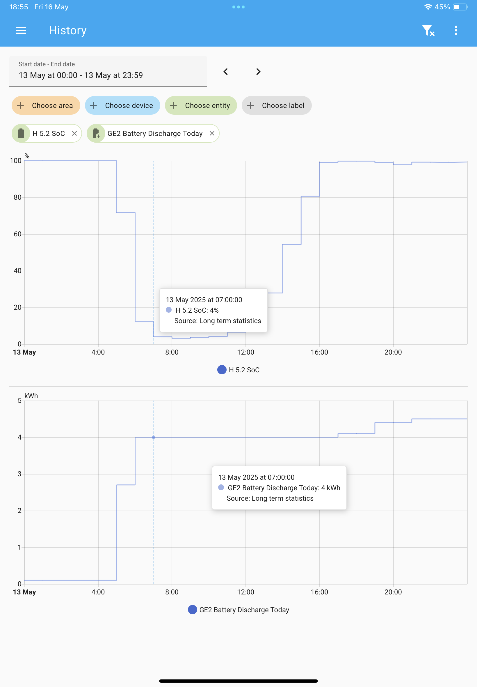
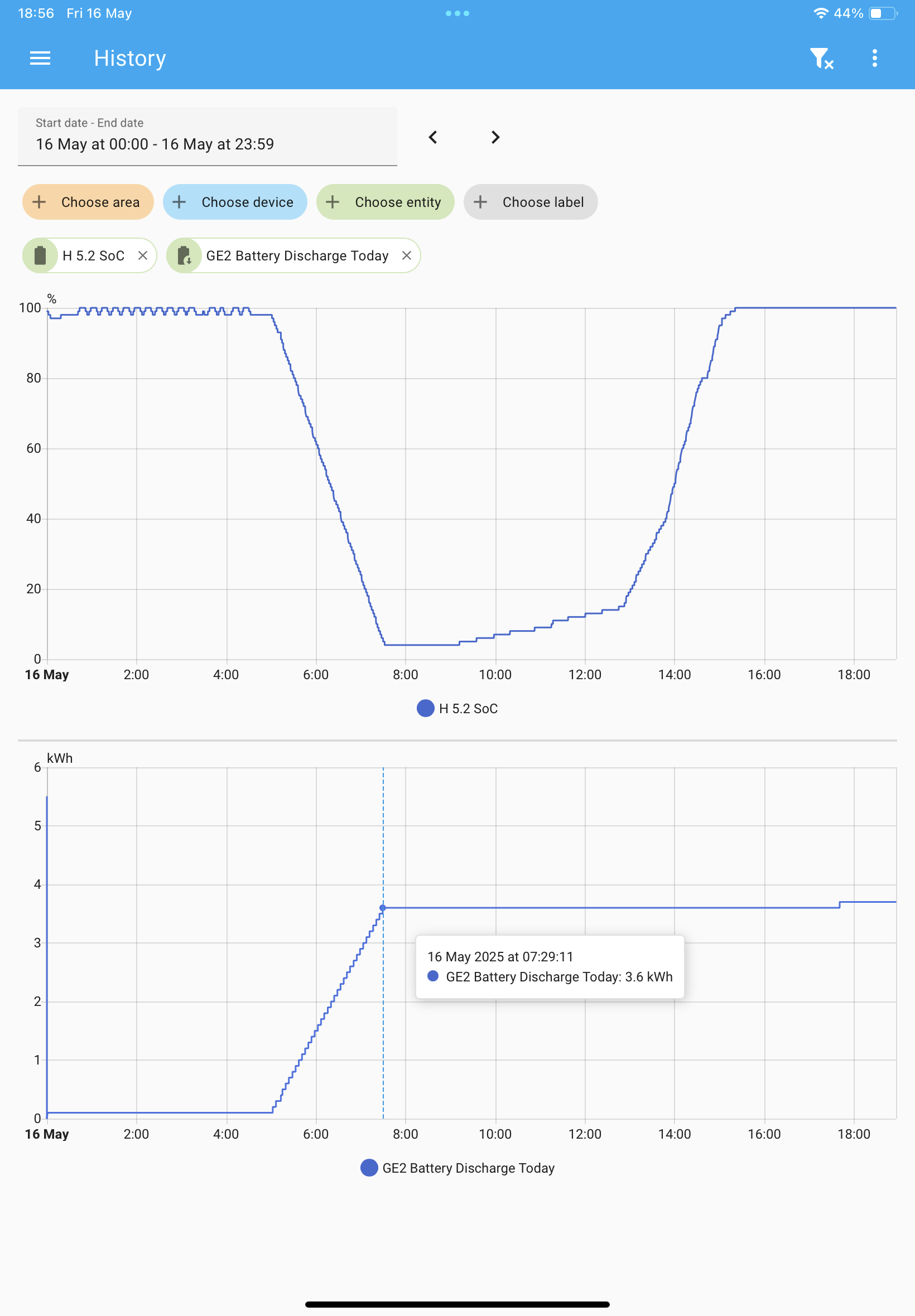
hoggy I believe we should be able to get just under 4kWh out of our 5.2 batteries:

5.2* 0.8 (DoD) =4.16 * 0.96 (taking 4% reserve off)= 3.994

With 3015 I was getting 4kWh discharge from 100% to 4% SoC:

With 3020 I today achieved 3.6kWh:

Not good

P
#13 Pete.J

I've seen cell voltages of up to 3.7V in one cell and as low as 2.3V in another. These two cells are in different battery packs. These values are extremes, but 3.65V is not uncommon for the too-high cell and 2.7V is not uncommon for the too-low cell.

Having an over voltage cell affects the calculated SOC for the battery because the combined battery voltage looks high enough, at least until the battery is loaded and the rogue cell drops to similar voltages to the other cells> This means sometimes I don't get the true capacity of this battery.

M
#14 mpartington

Wow, I've never seen more than 7.2kWh discharge on any firmware (so 3.6kWh per battery). I always thought the 4kWh was the amount each battery charged back up by (discharge being less due to losses)

I do have suspicious that the AC3 firmware under reads it though. On the old (slow) firmware, Max DC discharge was 3300W, and now it's 3130 W (ISH)

R
#15 Rubikcube

I have been working on some cell performance analysis software for the last few weeks. Unfortunately it won't be ready for general release for quite some time yet. But early results have revealed a surprise!

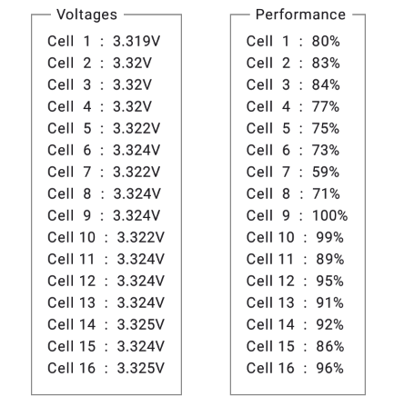
Cell 7 is the weakest (I knew that already), but the next weakest are 5, 6, and 8, which suggests that bank is weak overall. Looking at all the figures Bank 1 (cells 1-2-3-4) is showing around 80%, Bank 2 (cells 5-6-7-8) is below 80%, banks 3 and 4 are both generally 90% plus.

This suggests to me a possible issue at the factory where the cells have been assembled into banks of 4, but the banks have not been matched when assembling the battery.

#16 Windy Miller

Rubikcube What do the percentages indicate? One cell at 100% - is that a perfect cell or is that the best of the 16?

Looking back through posts problems seem to occur both with the cells and also with the connections. How might that show up in your data?

When I've used your app to follow the voltages there is usually one cell that leads the way at the high voltage end and at the low voltage end. Is that what is happening to your 59% cell? Sometimes it is a different cell at each end. Has the balancer caused this (I don't know what it does)?

A completely non-scientific check on 80 or so Amazon AAA cells all purchased together similarly shows some cells better than others yet presumably they were made at the same time on the same line so there must be quite large variations when the cells are manufactured. I assume this also happens with the GE cells. Then they age at different rates. Would a slightly weak cell when new become the worst of the pack over time as they hit the high and low voltage limits more often?

Lots of questions but what you're doing is fascinating. I look forward to being able to track my own batteries with it. Thank-you.

V
#17 Vestas

Rubikcube I'm not sure where you got this "bank" idea from but the cells aren't sequential. If they were then there wouldn't be temperature sensors for cells 1-4....

Cells 5 and 8 are busbar cells (or cable on early models) and take the brunt of the day to day abuse.

W
#18 wrighar

Vestas

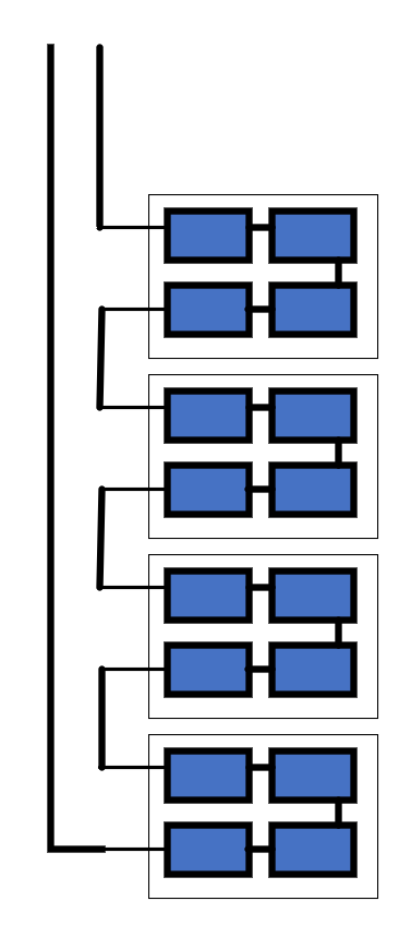
the 16 cells are sequential, but in 4 blocks of 4 connected by bus bars stack 4 high, 4 to a level.

-ve_____#-#-#-#____#-#-#-#____#-#-#-#____#-#-#-#____+ve

Temperatures are for bank or block 1, 2, 3 and 4

#19 hoggy

There is no sweeping statement, depends entirely on the battery - I have 2 blocks of 8 cells in an 8.2.
Temp probes are 2 in the top bank and 2 in the bottom bank.

9.5s can have 32 cells in 4 modules in some cases (2P16S)...

Newer Gen 3 5.2/9.5 ones (with the rounded front) I'd expect to have just 16 in again (probably 2 rows of 8), hence they shrunk in size

W
#20 wrighar

I think the new gen 3 9.5's still have 4*4, but they have just removed the void space at the top of the old gen 2 9.5.

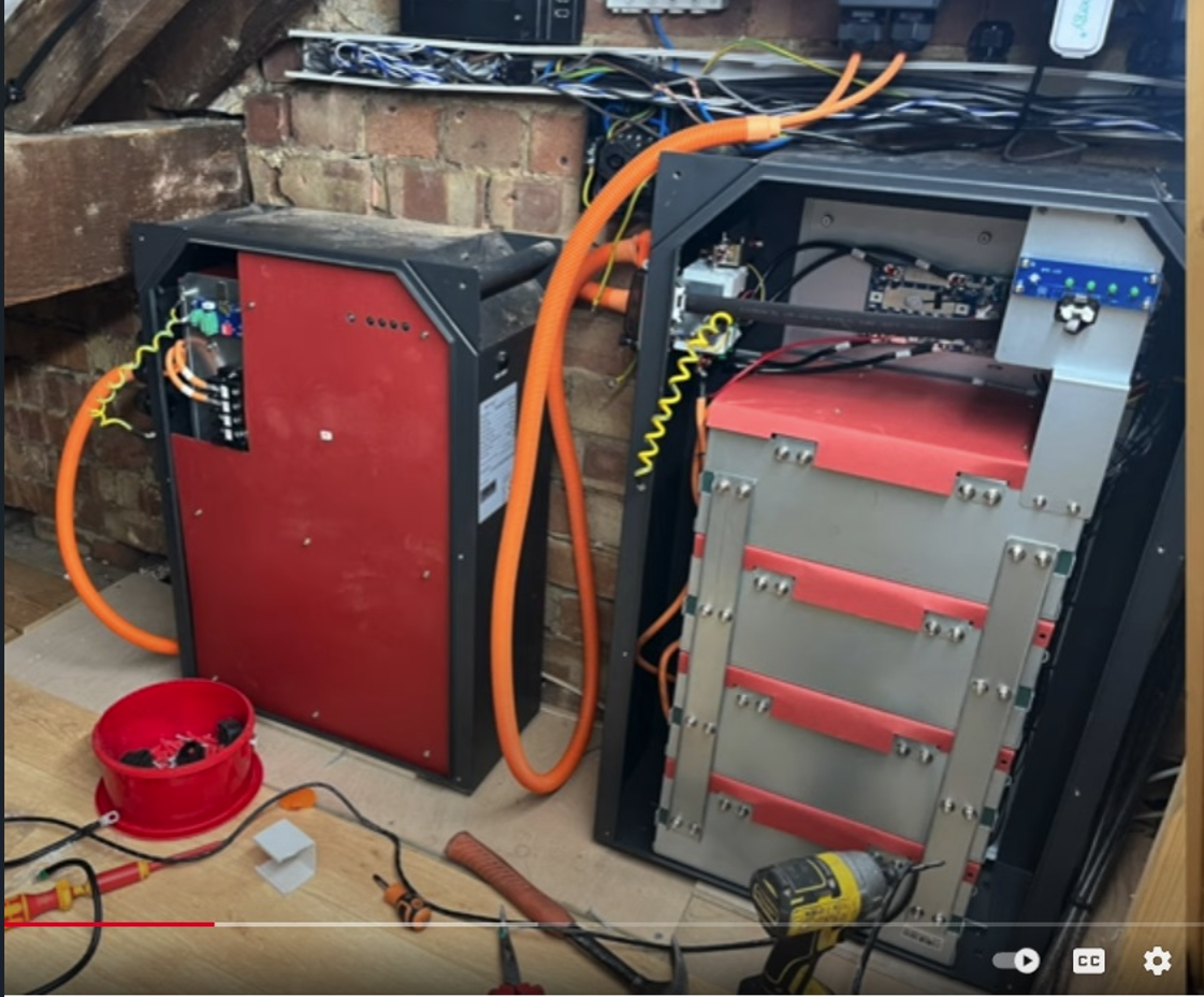
8.2 left, 9.5 right

V
#21 Vestas

[unknown] I understand how they're wired thanks 🙂

I know you know this bit but others might not....

Its the busbar cells which are usually the problem because the physical connection to the battery loosens over time due to heat expansion/contraction during charge/discharge cycles. Whatever locking compound is being used on the thread isn't up to the job on some batches, and maybe not up to the job at all for outside installs. There seems to be a consistent failure mode along these lines.

When the connection loosens then the electrical resistance rises and then you have increased voltage drop between cells/packs. The cell connected to the loose busbar gets hammered in terms of reduced lifespan - heat, overcharge, all sorts of battery unfriendly things.