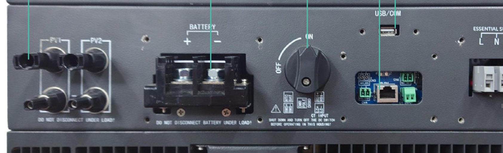
The spare router we were using as a wifi extender so that our inverter had enough signal has died. In the three years since we had solar installed, we've had a wired network added to the upstairs, which includes a network switch in the loft, where the inverter is.
So I'd like to move from wifi to a CAT5 wired connection. The trouble is, I can't find the network socket on the inverter, or any instructions. Does anyone have anything they can share with me to explain where the socket is on the inverter and if there is anything I need to do to get it working?
I can make a local wifi connection to the inverter, so I can get access to configure it if necessary. I changed it to use the main house wifi network, but it was only registering 42% signal, which doesn't seem to be good enough to get the app or cloud website working.
Thanks.
C
#2CW
JeremyGooch Um, I can't help with the specifics, but I think those who can, will need to know what inverter you have (it may not have the ability to have a hard-wired connection)
A
#3alan_johnston
What model and generation is your inverter?
If you have a gen1 like me, chances are you are stuck.
It only supports the WIFI dongle which is 2.4GHz, channels 1 to 11 only.
If it helps, I have used a TP-LINK WIFI access point which is cabled via the home network back to the router, and is positioned right next to the GE WIFI dongle so it gets a good 100% signal. It is set to 2.4GHz only and has a different SSID just for the inverter.
J
#4JeremyGooch
I'd put the model in the thread title. Is that not the right thing?
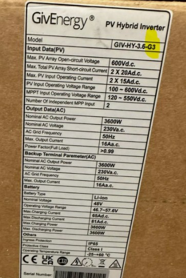
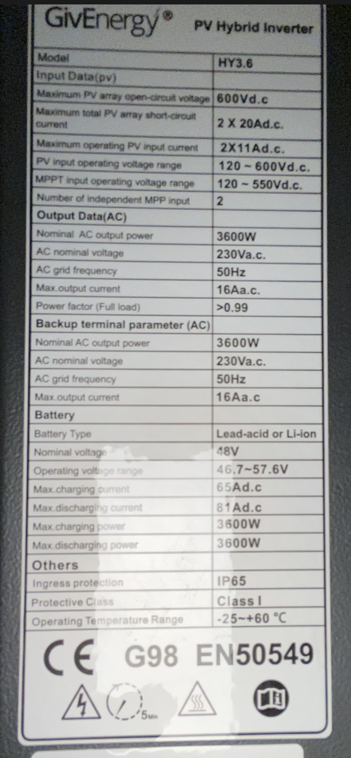
The docs from the installer just say GIV-HY3.6.
S
#5SteveCook
[unknown]
Jeremy. Please remember this is not a manufacturer/installer help site, it is just other users trying to help.
I believe there are 3 generations of Hybrid 3.6 inverter, and the question from Alan was to determine which generation, as some are wifi only.
S
#6SteveCook
is there a sticker somewhere with a G model
J
#7JeremyGooch
Sorry - that genuinely wasn't meant to come off as snotty. Tone and intent can be very difficult to interpret on t'Interweb. 🙏
J
#9JeremyGooch
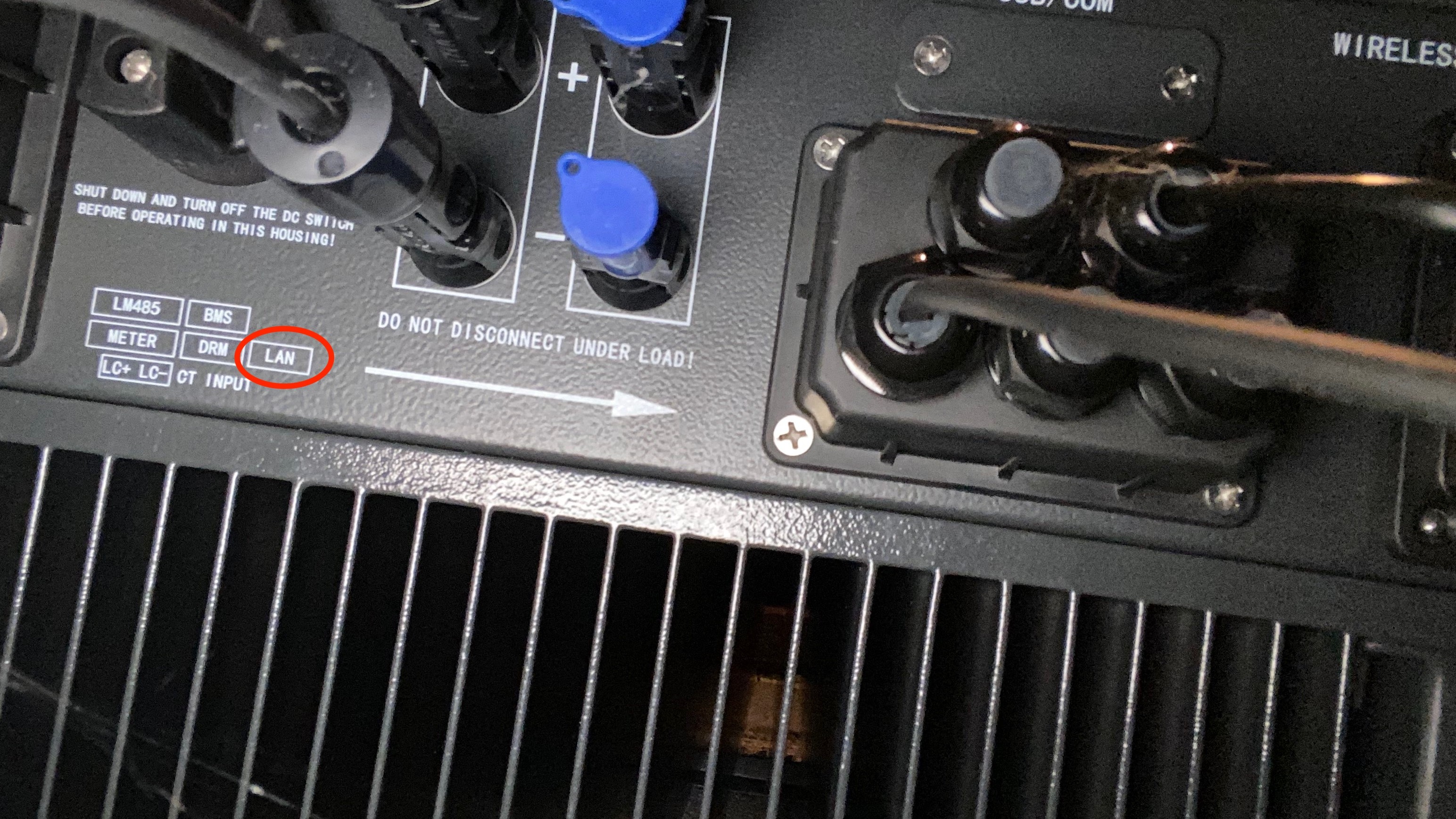
Here you go - picture the label on the side. I also took a picture of the underneath, as it has a box with LAN printed in it and an arrow, although I don't know what it's pointing towards.
It's toasty in the loft. 😅
C
#10CW
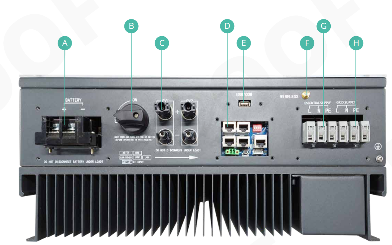
Looking at the photo of the bottom, this looks like it is a Gen 2 inverter (see installation manual
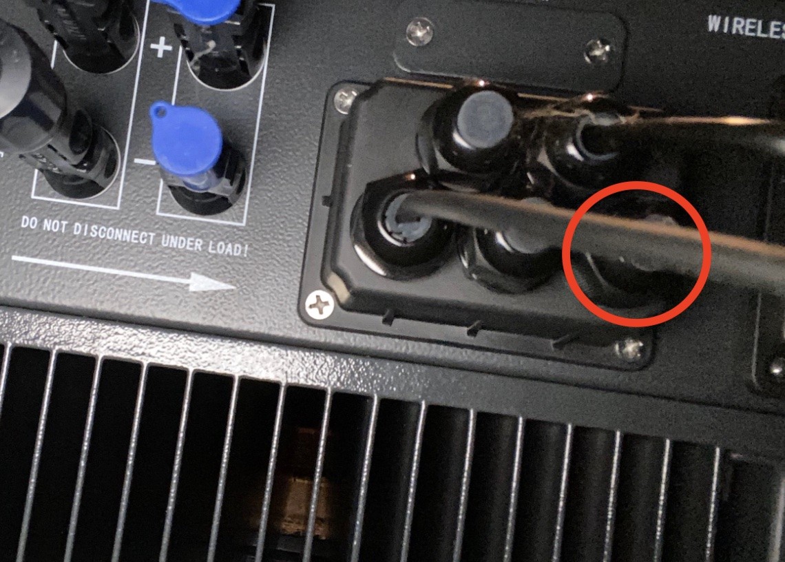
Awesome! Thank you. So I ought to be able to undo this thing (picture 👇) and plug a LAN cable in? Do I need to power everything down? The stuff labelled "D" in the first picture you've posted looks network-y, so should be safe?
C
#12CW
I'm not an installer etc. but if I were doing this, I would make sure the whole thing is switched off before I started any work. I havn't read the installation manual so you may get some pointers there as well.
As an aside the markings to the left of the long arrow look like they describe what each of the ports under that cover do (at least that is how I read it)
S
#13SteveCook
No problem
i think you have to take the shroud off - 4 Philips screws - and slide the shroud down the connected cables. Make sure you dont pull out the other cables. I am not sure if the BMS has a latch (my gen1 does not and it fell out).
The feed your new LAN cable into the shroud and plug it in to the inverter.
Not sure how much space is there, you may have to get an un-terminated cable through the shroud and then put an RJ45 on the end.
I then pulled a couple of inches of slack into the shroud, bunched them and taped them so they could not accidentally get pulled out of the inverter.
I think there is a DIP switch somewhere that needs setting for LAN.
Put the shroud back on.
Good luck
M
#14mrand31
I'm not sure if the later versions had any, but the Mk1 version did not have any components in the circuit board locations for electrostatic protection of the battery and meter interface connections. This meant that it was possible to damage the interface if things were unplugged/plugged in while any part of the system was powered up (as I found to my cost). So best advice is to shut the entire system down (solar, battery, grid/mains mater then inverter) before removing the cover.
Other than that, it should be simple.
Beware that the screws like to fall off the end of the screwdriver and hide in dark corners when you remove them. 😃
#15ChrisLav
mrand31 ...and, to avoid any electrostatic charge coming from yourself and/or clothing, ground yourself by touching part of the frame before poking your fingers into the works. Processors can be very sensitive...
J
#16JeremyGooch
Beware that the screws like to fall off the end of the screwdriver and hide in dark corners when you remove them. 😃
Ha ha! That's the truth.
Thank you, everyone. I'll power it down (when it gets cooler) and investigate under that panel.
#17TheDragon (GivEnergy)
[unknown] ensure the DIP switch is set to 0111 instead of 1111, to put it in LAN mode.
You can then if you wish remove the antenna, replace with a dummy SMA connector, removing the wifi signal
J
#18JeremyGooch
Thank you for all the information. I'm very nervous about shutting the system down and changing the switches. I've started a new thread about ongoing wifi issues here, in case by chance someone can tell me how to get the wifi back up.
Otherwise, I think I'm in a world of needing to get someone out to look at this.