EPS changeover switch hardware

121 comments started 2023-01-21 last 2023-05-18
GivEnergy ProductsAC Coupled
6
#1 666tim666

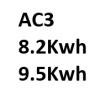
I wish to fit a changeover switch or switches to manage the supply to an EPS CU from an AC3 and givbat9.5.

The load will not exceed the EPS output and so I can afford to have automatic changeover. It is presently my intention to have the CU powered from the grid first, and then when that fails to switch to power from the EPS output. That way, by default, maintenance of the inverter or battery system will not interrupt power to my EPS CU.

So I am looking for hardware to achieve the automatic changeover. Has anybody done this, and if so using what switching kit? I have all the wiring in place, and my original installation electrician allocated, and so any suggestions would be discussed with him to source and fit the kit.

S
#2 SteveCook

Have you look at the KB for the best way to wire this.
https://kb.givenergy.cloud/article.php?id=12

Does the AC3 have an EPS output?
Why complicate things as you will have to have something that senses mains failure - when you already have this built into the inverter.
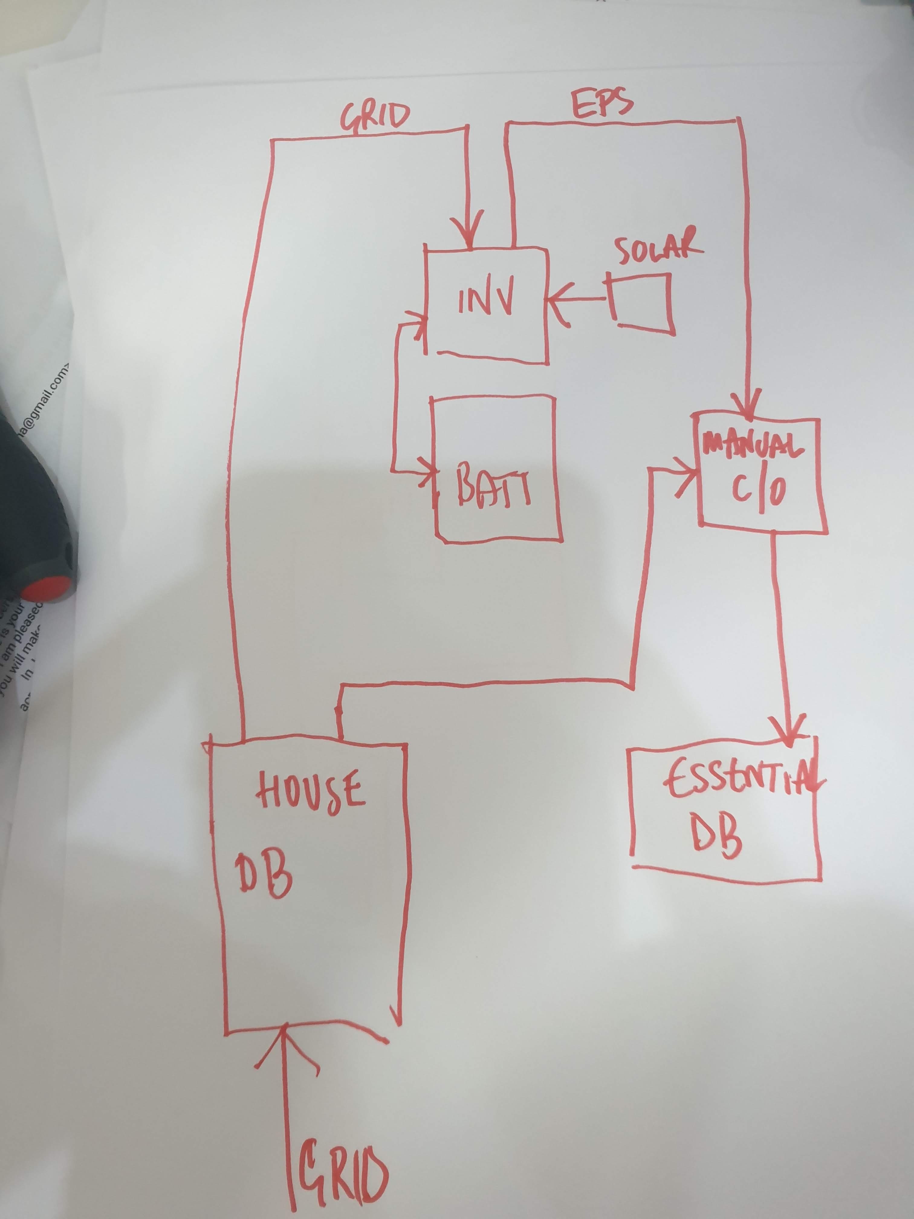
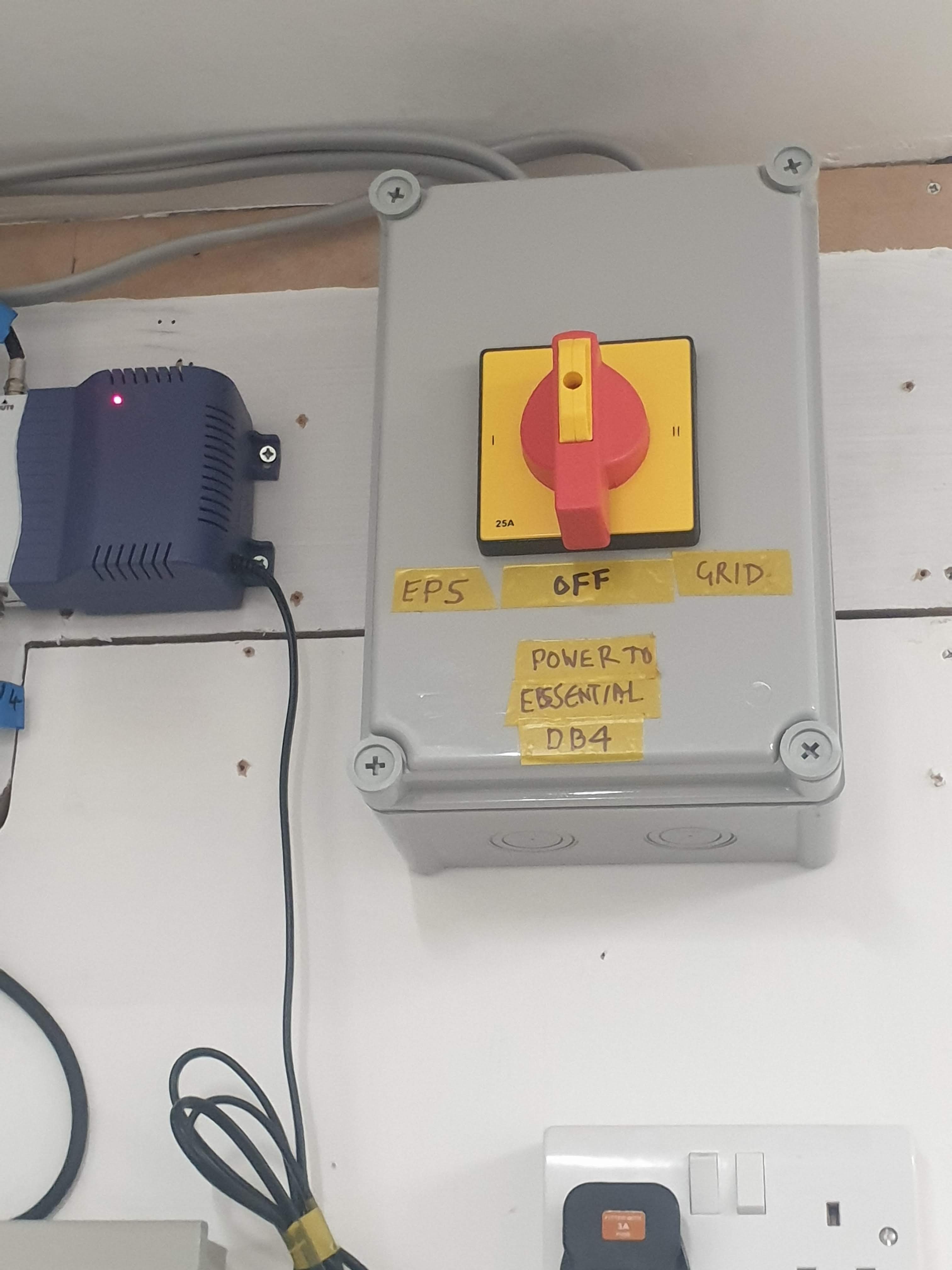
Feed the essential CU from the inverter EPS output via a 2 way manual changeover switch.
The other input to the 2 way changeover switch being the mains.

In normal operation the essential CU is fed from the permanently live EPS output. When mains fails the EPS will continue to feed the essential CU.

With grid mains "on", just switch the 2 way changeover switch to grid input and shutdown the inverter for maintenance.

Don't forget you must have a TT earth

6
#3 666tim666

SteveCook Hi Steve, thanks for your reply.

Complication arises because the inverter is a sophisticated and complex device which could fail, and given recent discussions on this forum, very likely will from time to time.

Now when I am not at home, and my fridge and freezer are full of valuable goods, and my solar hot water panels are subject to sunshine which, in the event of power failure will 'stagnate', and the copper pipes will reach red heat, I don't want a grid outage or an arbitrary inverter error to disconnect the power. So I will have either no ESP - ie the ESP CU will be connected to the grid only, which is probably more reliable than the ESP output on the inverter, or I will have an automatic changeover.

Yes, the AC3 has an EPS output. And yes, the TT earth is already fitted, thanks for pointing it out.

So, does anyone have automatic changeover hardware and what is it please? I know it exists because people have generators that power their house in the event of grid failure, and the systems start automatically and switch over automatically.

S
#5 SteveCook

666tim666
Really how bad/unreliable are the inverters.
What is the experience on here of inverter failures - I am sure they do not need regular maintenance. What is to maintain.

6
#6 666tim666

SteveCook Thank you Steve for your reply.

You are right, maybe. There is some experience on this community of hardware failures as people have reported that kit has to be replaced and sometimes it seems to take a while. I don't know if that applies mainly to inverters or to batteries. But GivEnergy are not very forthcoming with MTBF and MTTR figures, are they.

Maintenance would seem to be mainly firmware updates at present, and experience on this forum of testing the new software recently suggests to me that the application of updates is a bit random and unpredictable. I don't think that I would leave my house with critical circuits running from the EPS output on my inverter at the moment.

6
#7 666tim666

Rubikcube Thank you for your reply.

I agree with you that ATS hardware is expensive. Although there are cheaper switches on Amazon, I don't think they come into the category of 'approved for use on fixed wiring in the UK'.

But there are a lot of people using ATS hardware in their houses and on mobile homes, boats and the like and so there should be something off the shelf which would do. The current carrying demand is small and there is no requirement to send signals to generators and monitor their startup, shutdown, etc, and so only the most simple example of an ATS device is required. I will continue looking.

I
#8 ispookie666

I did make up an ATS using DPDT relay and two contactors a while ago for running a fish tank from mains and backup power. It's not complicated, plenty of guides online, but don't know the Electrical wiring guidelines.

I think I used Omron (bough from RS pro, please don't buy anything from eBay) and Schneider contactor.

I went through two versions
First was using two DPDT relay and the second using one DPDt relay and two contactors. I think it cost me around 60ish.

6
#9 666tim666

ispookie666 Yes, I have drawn up an ATS circuit using RS contactors and Broyce time delay relays but it wouldn't comply with the wiring regs.

J
#10 JMalcolm

I recently asked the installer of my system (Hybrid 5kW with PV and batteries) to quote me for a auto switch and installation of a TT earth. Idea was to power the whole consumer unit from the EPS in the event of grid failure (mainly if we are out to power the fidge/freezer). Obviously not looking to run anything high load on it.

We were quoted £2k so, as Rubikcube said above, the cost is hard to justify.

I
#11 ispookie666

JMalcolm sounds excessive.
My installer has put in a contactor in the separate DB, which contains all and backup circuits. It has worked when I have tested, but I had problem with the Inverter board getting fried. This was blamed on lack of earthing, the only problem was - I already had TT in addition to TN-S.

R
#12 RBilton

ispookie666 I’ve had a manual change over switch fitted on output of EPS. I also had a TT Earth done. It all tested ok back in late summer, we only used it for essential circuits such as freezer and led lights. I now have a non generating inverter and 2 flat batteries. This failure happened 15 Jan, support say there’s a failure showing on my EPS but it’s all switched off and has been for months.

I
#13 ispookie666

@RBilton I hope this gets sorted quickly. Mine took a lot of time, compounded by christmas and holidays.

R
#14 RBilton

An engineer from GivEnergy came on Tuesday and sorted it, I was very impressed with service and technical expertise.
Thanks also to EcoPartners, the original supplier/ installer who got this all moving quickly.
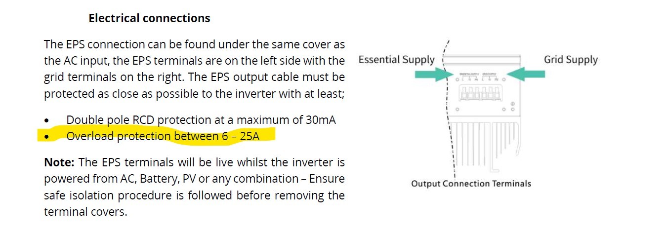
I’m back where I need to be, lots of generation and storage.
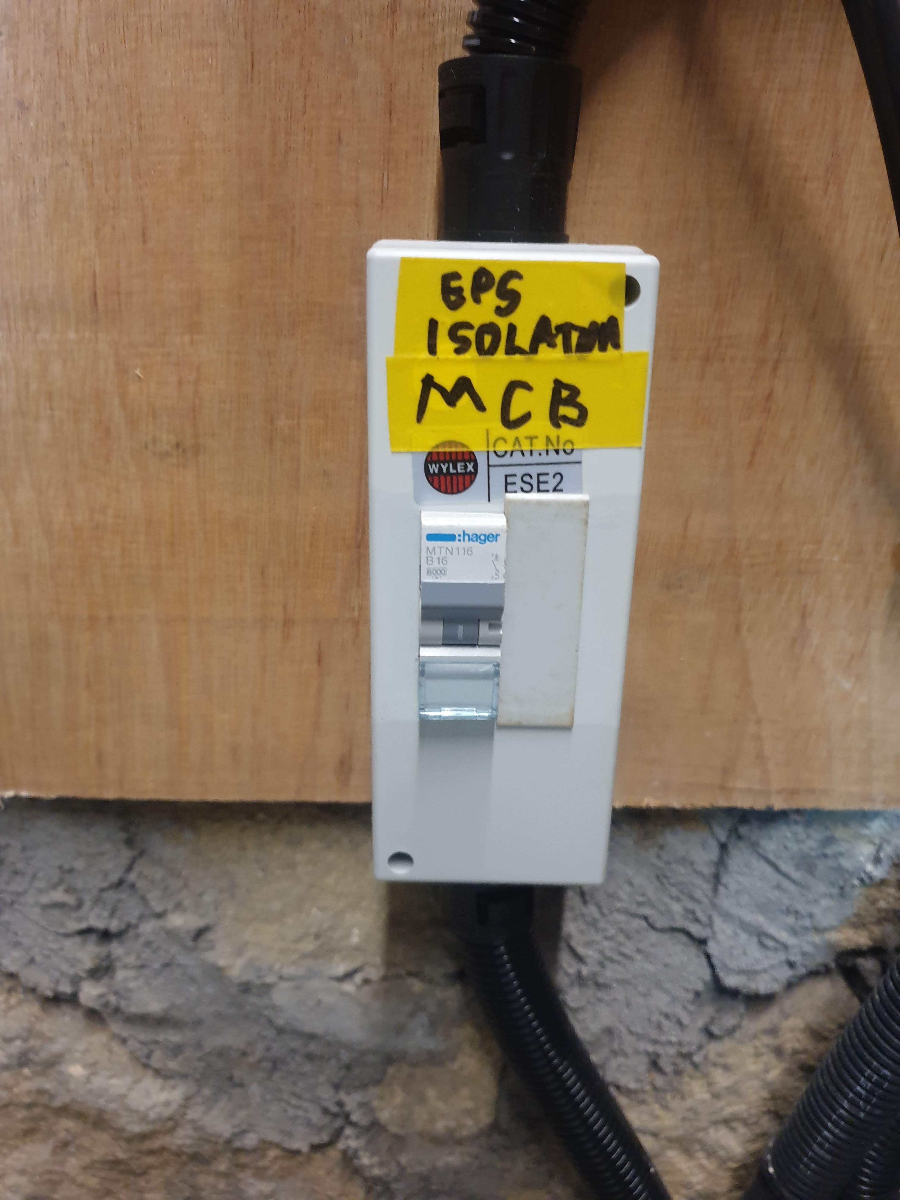
😀

S
#15 SteveCook

RBilton I’ve had a manual change over switch fitted on output of EPS. I also had a TT Earth done. It all tested ok back in late summer, we only used it for essential circuits such as freezer and led lights. I now have a non generating inverter and 2 flat batteries. This failure happened 15 Jan, support say there’s a failure showing on my EPS but it’s all switched off and has been for months.

My understanding is that the EPS should always be running under load with power going through it from the inverter all the time.
When grid supply drops out, the normal output circuits of the inverter go off and the EPS stays powered, though there may be a small interruption of supply as the electronics kick in
The manual changeover switch is to disconnect the EPS output when maintenance is needed on the inverter and switch the essential circuits to grid power. 2 inputs to the changeover switch (grid and EPS from inverter) and 1 output (essential circuits).
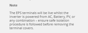
If inverter needs to be worked on, shut it down and flick changeover switch to grid. Open inverter breaker on normal circuits on consumer unit and open breakers to PV strings , disconnect battery and inverter will be fully disconnected to be worked on or removed and house essential and non essential circuits will be grid fed,

K
#16 kram

https://www.justgenerators.co.uk/generators/accessories/power-transfer-switches.html

Manual cheap, automatic less so.

However on the wiring I have heard on plenty of systems where the EPS Outputs are wired to an input on a manual changeover switch. The other input being the grid.

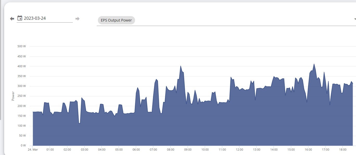
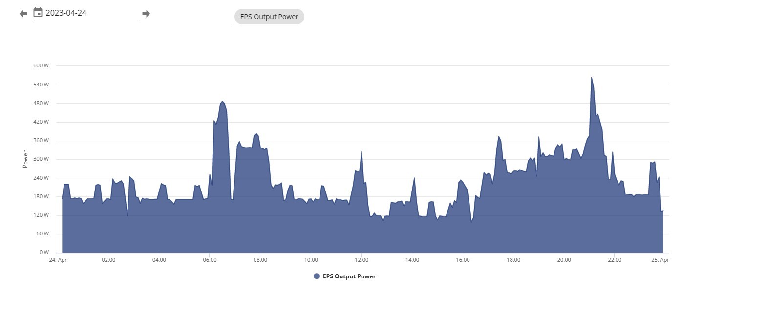
When power goes the owner makes sure the load is below that of the battery/inverter EPS output and switches the input from grid.

EPS kicks in and runs the chosen circuits from battery output.

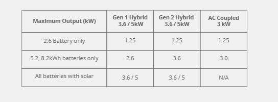
If you have the required items, fridge/freezer, boiler, lights and maybe a double plug to keep internet up and charge phones on separate circuits/DP with total load possible below max battery output then you could go automatic.

T
#17 Toogie

SteveCook

My inverter story.

In Nov 22, I got a local GE approved installer to add a 9.5kW battery, manual EPS and TT earth circuits to my year old 4kWp PV, 3.6 hybrid inverter and 8.2kW battery system which had been performing well up till then. It took three visits to complete the installation and commissioning due to a missing pcb in the inverter which had to be ordered and two all-in-one to ring cables not being ordered as I initially requested. I was not at home when the EPS facility was tested and I have not needed to use it so the c/o switch has not been touched.
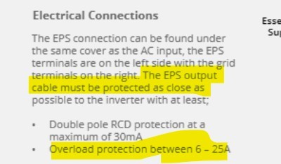
All went well until 24Jan when I awoke to discover a data loss at 1030 pm the previous night and the inverter in idle mode, the batteries hadn’t charged overnight so we’re pretty flat and the PV voltage was almost zero. The GE help desk said the system was showing a comms failure from the EM115 meter so when I checked the meter cupboard, I found the EM115 16A rcd had tripped. I reset it as advised by the engineer but he could not force a charge into the battery pack and was puzzled by the PV volts drop. He asked me to call out the local installer and eventually on 31 Jan at a site meeting, GE and the local engineer concluded there had been a burn out in the inverter and requested a GE warranty call out to replace it. This should have happened on 3 March when Steve came with instructions to repair the 9.5 battery not the inverter -so had not brought a replacement inverter. Crossed communication wires meant he returned the next working day and did a great job of installing a refurbished inverter under warranty, updated the 8.2 battery firmware to match that of the 9.5 and corrected several comms wiring errors and set the batteries to calibrate which they did over the next ten hours. He was here less than an hour and left everything working perfectly- totally impressed for once!
He said he had not come across a failure like this before so it remains a mystery but my gut feeling is it was something to do with the comms wiring.
Hope this adds to the user knowledge base.

6
#18 666tim666

SteveCook I am interested to see that this thread is still going. I suppose that's not surprising.

Faced with a high cost for an ATS, my installer has recommended a manual switch, with or without a simple relay contactor to automate the change over. He has suggested that, if I want the relay, it should be set to operate from the grid and not the EPS output, by default. This would mean that, at the point of grid failure, the relay would transfer the EPS circuits to the EPS output, and that at the point of grid recovery, the load would transfer away from the EPS output back to the default.

I have suggested one amendment, to add a broyce delay relay on the control input to the contactor so that, when the grid voltage restores, there is a delay before switching. I have suggested 15 seconds to allow for those failures of the grid which don't restore cleanly. I think such a precaution is common on many electronic devices to protect them from grid errors and I would hope that the Givenergy inverter is itself so protected. My solar inverter (separate pv installation) messes about for minutes checking the grid supply voltage and frequency before reconnecting.

If I understand you correctly, you have suggested that the EPS load should by default run through the inverter. Why?

The EPS load is going to be varied, although in my case I don't expect it to ever exceed 1Kw. But I would expect the load to go up and down, and also that I could go to the designated EPS CU and switch it off or on at the switch disconnector at any time whether operating on the EPS output from the grid or the battery. And also that I could operate the manual changeover switch at any time without causing a problem. The load includes a fridge, a freezer, and several electronic devices, and this is not clean like a resistive load. If the EPS output is sensitive and fussy about the load and might break, then maybe I should reconsider the whole idea.

What do you think? Do you think the EPS output is fussy about load variation?

#19 THALL

666tim666 1kw should be fine, if there is a chance it might be over 2.5kw then its likely to trip.

S
#20 SteveCook

This is what I have done
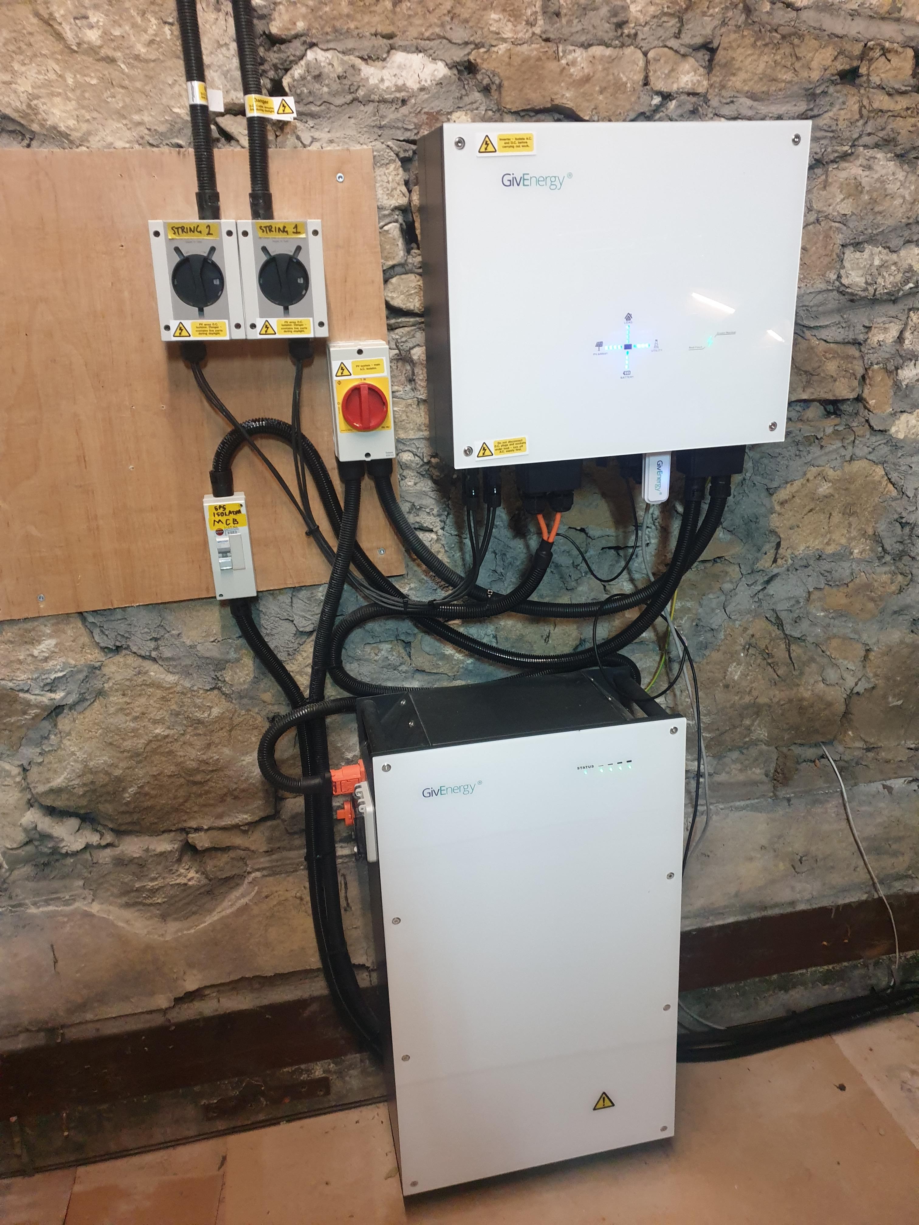
In day to day use the CO switch is set to EPS and the inverter feeds the permanently live EPS output through the CO switch and into the essential DB.
I have the essential DB with only the following circuits on it fridge and freezer, gas boiler pump and controls, smoke detectors, lounge power (tv and skybox), lounge lights and socket for router. That lot is about 500w so will not overload the EPS.

When I flick main breaker at house BD to simulate grid failure everything on grid goes OFF
Essential DB fed from EPS goes off for a few seconds (maybe 5 max) and then comes back on.

When I close house DB main breaker to simulate grid back on, essential DB stays on and grid stuff comes back on.

The CO switch just allows me to take PV/battery/inverter offline for maintenance and the essential DB will be direct grid fed rather than via the inverter EPS

6
#21 666tim666

THALL Thanks for your reply.

When you say the EPS output may trip, what do you mean? Does the EPS output electronics monitor the load and switch off if it exceeds the maximum. Or is there a simple automatic cutout of some sort. And is reset manual or automatic?

Or does the electronics monitor temperature and decide that its reached a maximum threshold?

And if the EPS output does trip, then is this status visible in any givTCP data?

Thanks.

6
#23 666tim666

SteveCook Thanks for that explanation and diagram Steve.

Yes, what you have done is one solution that I am considering. I have a few more things on the load, including all of the house lights and some desktop computers, but not the TV - well not at the moment.

Given that there is a delay with EPS output when there is a grid failure then my proposed relay contactor should work OK because it would change over to EPS output during the few seconds (maybe 5 max) that the inverter is using to switch.

6
#24 666tim666

SteveCook Thanks for your reference to Givenergy documentation.

The explanation doesn't suggest that there is likely to be a problem unless the inverter max. output is exceeded although having a buffer to take account of tricky loads is probably wise. My hot water circulation pump alters in speed according to the temperature difference between the panels and the store. The controller manages the speed by turning the power on and off all of the time. It is a similar technology to a light dimmer. But the switching power looks like a messy load for an inverter.

My microwave on defrost similarly turns the power on and off all of the time (its not a part of my EPS load) and it really interferes with the inverter's ability to track the house load - so much so that we don't use the microwave on defrost any more - just on maximum for a short time and wait a minute and then do it again if necessary.

S
#25 SteveCook

666tim666
The EPS output on the inverter is always live.
When grid fails, it is the grid connection on the inverter that goes DEAD to prevent electrocuting anyone working upstream on the network, particularly if the sun is out and you are in export mode

S
#26 Slartibartfast

Quick observation. When the inverter looses AC power it shuts down Modbus i.e. doesn't talk to the ID1 or ID2 meters. It also doesn't update the battery LED display. The inverter slowly drains the battery 20-25W until it gets a BMS Undervoltage fault. The it powers down. The LEDs were still showing >75% when it shut down.

T
#27 Toogie

Steve,
I like the config. How do you accommodate the two different earth requirements?

T
#29 Toogie

Can’t argue with that then-cheers

T
#30 Tim

SteveCook Essential DB fed from EPS goes off for a few seconds (maybe 5 max) and then comes back on.

AFAIK EPS circuit can be configured (by Givenergy) to be no-break ie UPS. I think @TheDragon (GivEnergy) has this set up on his EPS. IMO, having the "essential" consumer unit fed from EPS through the changeover switch is a better way to run the plant, just using the switch to disconnect the circuits for inverter maintenance. Doing this means that when there's a power cut while you are away from the house, the essential circuits carry on without any intervention from anybody.

S
#31 SteveCook

Tim
Exactly. As long as the expected essential CU draw is less than the EPS can deliver

#32 positor1

should the em115 meter be fed from the essential CU?

S
#33 SteveCook

positor1
What would/could be happening at EM115 as no grid can be coming in as grid is dead, and no power can be going out as inverter is islanding

#34 positor1

But if powered it would still be able to report zero everything to the inverter.

T
#35 Tim

positor1 that sounds like a sensible idea. The inverter would be internally electrically disconnected from the grid consumer unit but powered from PV/battery. Does anyone know where grid voltage is measured? Is it by the EM115 over Modbus or at the inverter from the grid consumer unit connection? If by the EM115, it could be confusing if it was fed from EPS but if by the inverter grid connection then it would be obvious what the state of the inverter was.

S
#36 SteveCook

positor1
hmm, good point
Bit of a problem for me as EM115 is next to meter and powering it from the essential DB would need me to run 15m of cable through a route that will be very difficult without decorations required.
I don't think my wife would be happy

#37 positor1

SteveCook
so is the consensus that it would be optimum?

S
#38 SteveCook

my EPS powering essential CU constantly while rest of house is grid fed
load ramps up as lights get turned on

M
#39 michaelmcgoldrick

Hi folks,

Could someone show a picture of the EPs connectors with the cover off a gen2 hybrid inverter? Do you have to unscrew the four screw's in corner to drop it down? Electrician going to wire for me in a few weeks. Also does anyone know how far the EPs socket can be from the inverter? Would you see a drop in voltage if you ran say a 30 meter cable? I don't intend to but it would be far more convenient if we could

T
#40 Tim

michaelmcgoldrick Your installer will know what size cable to put in to ensure that your voltage drop for the maximum rated load (ie not what you think you'll be drawing) is within the regulations. They will also know what sort of protection to put on the cable (fuse or MCB) to ensure there is no danger should the cable develop a fault. Given this, if you wanted to run the cable to a consumer unit or switched socket 100m away, they'd just size the cable accordingly. The cost of different sized cables is marginal compared to the labour costs, so let them put in the biggest cable they want and ask them to put it in the location most convenient to you.

S
#41 SteveCook

Well since the EPS changeover switch has been installed (about 4 weeks) I have had 3 RCD trips on the mains feed to the inverter.
The distribution board has a single main RCD, and so everything goes off in the house and then the EPS cuts in and feeds the essential board.
So all working correctly, but random trips taking out the rest of the house is not what I want!!

I now see the new GE Installer Training Manual V12 has a new clause that if the inverter has an RCD it must be it's own circuit and not shared with other circuits. This clause was not in previous versions.

I have now replaced the main RCD with a main switch and put RCBOs on individual circuits that need them. MCB just for the inverter.

I guess the inverter/battery may do funny things with current and wave forms and RCDs may be subject to nuisance trips.

I will see how it goes.

R
#42 Rubikcube

SteveCook I now see the new GE Installer Training Manual V12 has a new clause that if the inverter has an RCD it must be it's own circuit and not shared with other circuits. This clause was not in previous versions.

Correct, but not complete. Most household circuits should be protected by a type AC RCD. Battery inverter should be protected by a type A RCD. Hence you should not share them.

RCD tripping is caused by a wiring fault. Random trips are almost always neutral-earth faults. Neutral-earth faults without RCD protection are a leading cause of house fires.

#43 positor1

Rubikcube
a fully populated RCBO "essentials" consumer unit would surely comply and be the best option would you agree?

S
#44 SteveCook

Rubikcube
Hi
I have run 4 years without a random trip.
I have run 3 years with SolarEdge system without random trip.
I have run 6 months with GivEnergy system not using EPS output.
Making EPS connection has caused random trips, but that only involved the addition of a single wire.
I have been a Chartered Building Services Engineer since 1986 and both PV installations were done by NICEIC contractors, and I subconsciously look for incidences - toaster, washing machine, iron, kettle. There are no coincidences

When there has been a trip, I have opened all breakers on the shared RCD and the tried to reset the RCD. It will not reset whilst the inverter is "in circuit".

Why has GE literature now changed to now say not shared, when there was no mention of this in previous versions?
Does something happen with neutrals in the inverter/battery setup when it does "things".

S
#45 SteveCook

positor1
Yes, but what about cost.
Why not go the whole hog and fully populate AFDDs

#46 hoggy

When in EPS mode it makes its own neutral earth bond at the inverter - but should only do that when the grid fails and the EPS relay switches over. Rest of the time it essentially is an ornate junction box linking the input AC to your EPS circuits.

These GE inverters do also already have RCD protection built in but because you can't really test it like you would a normal one it shouldnt be relied upon.
https://kb.givenergy.cloud/assets/RCD%20Declaration.pdf#viewer.action=download

R
#47 Rubikcube

SteveCook

Exactly the symptoms you would get from a neutral-earth fault.

A simplified explanation: Electric current flows between live and neutral, and in a correct installation the current in the live and neutral is the same. An RCD detects and trips when the current in the live and neutral is not the same. With a neutral earth fault some of the current that should be returning in the neutral is finding an alternate route (back to earth). By adding a cable, you have increased the resistance of the neutral wire. This increases the proportion of the current "leaking" via the alternative route.

Normal work by electricians will not pick up this type of fault. In theory an EICR should pick this up, but in practice electricians have little understanding of solar equipment (because it isn't covered in their training) and may not know how to test an installation with EPS circuits.

R
#48 Rubikcube

SteveCook

Just to add, your electrical fault will be nothing to do with your solar installation. Probably a faulty light fitting or something like that.

S
#49 SteveCook

Rubikcube
Thanks
But for 4 years since moving in I never had a nuisance trip.
Adding solar and for 6 months without the EPS circuit connected I never had a nuisance trip.
Now with the EPS output feeding the exact same consumer unit that it has been feeding for 6 months (no other modifications) I get nuisance trips on the main RCD in the consumer unit feeding the inverter. Switching out all other circuits does not allow the RCD to reset.
I am EurIng, FCIBSE, MInstE, BSc and Chartered for 36 years so I do know my way around electrical design - not trying to be sarcastic.
Regards
Steve

A
#50 athresuk

SteveCook
What is your background earth leakage during normal operation ?
You could try a ramp test with a MFT to see how much you have.

It could be that you are marginal on available head room due to accumulative leakage on other circuits hung off that RCD (another reason why the GE guidance is to not have the inverter shared with other circuits) as PV inverters are leaky.

S
#51 SteveCook

athresuk
Sorry
I have no idea.
For now I have gone down the RCBO route to separate the inverter from the other circuits and so far no trips

R
#52 Rubikcube

SteveCook 4 years since moving in

The EICR from when you bought the house should have highlighted any issues with the electrical wiring.

S
#53 SteveCook

Rubikcube
Thanks
There were no issues. I have not had a nuisance trip in 4 years.
House was fully rewired 2012
They have only occurred since connecting the EPS output to the essential consumer unit that was fine for 6 months when running the essential consumer unit on the inverter mains output

6
#55 666tim666

SteveCook Steve, as I understand it a part of your house is on the EPS output and another part isn't. It has been known for electricians to share neutrals on lighting circuits - well in a manner of speaking it is quite normal and is no problem on a single final circuit. However I have seen cases where they become muddled, eg when an upstairs light has two way switching and one of the switches is downstairs, in the same wall box as a different final circuit. So an upstairs light ends up with a downstairs neutral or vice versa. This could also happen with a wrong choice of a live conductor of course and then that is potentially more dangerous. These cross connections have no impact if the final circuits are on and working and so a householder may have no knowledge of the issue.

Cross connection of protective earth circuits should be assumed (eg two final circuits in one box, both earthed to the box, or, earth connection on your plumbing and also earthing through an electrical item on a pipe, boiler or tank) and should not cause a problem.

So, is there any possibility that you have one circuit on your EPS and one not on your EPS with a cross connected neutral? Or any neutral cross connection between CUs etc.

I have an interest in this as I wish to follow a similar EPS scheme.

In case it matters I think RCBOs are single pole and may not therefore isolate neutral even when off.

S
#56 SteveCook

666tim666
Hi
The lighting is all done via RAKO units where all the lighting circuit cables run back to each relevant RAK unit, so I don't think it is that.
Don't forget when I switch the changeover unit to grid, the EPS board is fed from the house board and then share same neutral and earth.
I have not had any nuisance trips in 4 years pre GE install.
I did not have any nuisance trips post GE install when the EPS CU (obviously would not function as EPS at that point) was mains grid fed.
Only had nuisance trips with EPS circuit connected to EPS CU and at that point no way the RCD would reset unless switching EPS board to mains via CO switch and then back again.

Since taking RCD off the half of the split main CU and fitting RCBOs to the other outgoing ways, there have been no nuisance trips and if I kill the mains, the essential CU kicks back in after about 5 seconds and I just have to wait while the Skybox reboots!!!

S
#57 SteveCook

666tim666 So, is there any possibility that you have one circuit on your EPS and one not on your EPS with a cross connected neutral? Or any neutral cross connection between CUs etc.

No
I don't think so. The CU I used to become my essential CU was the one that only ever fed each RAK unit for lighting and had 4 spare ways.
I used these spare ways to feed 4 existing circuits that were dedicated radials. smoke detectors, fridge/freezer socket, router socket and the lounge power ring.

6
#58 666tim666

SteveCook Thanks for explaining that. Difficult to explain it unless the inverter is doing something that we don't know about.

Do you have the inverter main connection on an RCD or RCBO now, or just an MCB?

I have a separate solar PV system using an Aurora inverter. It was connected on a CU which had an RCD main switch. Occasionally the RCD would trip, disconnecting the garage (which I wouldn't notice quickly) and the inverter of course. This was annoying because of the loss of solar PV output while the thing was disconnected and if I wasn't there it could be for days. I think the fault occurred when the roof was wet, and that it was caused simply by capacitance between the roof mounted solar kit (panels and wiring) and the roof. Inspection of Aurora documentation confirmed that there was a problem and that the inverter should not be connected via an RCD. So now I have a split box with the inverter on an MCB and plain mains switch - no RCD, and it works fine.

My new inverter, the givenergy AC3, is on the RCD protected end of the CU, but then it doesn't have solar panels connected to it and so the above issue doesn't apply in my case.

S
#59 SteveCook

Hi
The main consumer unit for the house is a 32 way split unit.
Both sections were RCD.
Now the bottom is main switch and RCD and the top section is main switch with RCBOs to circuits with MCB to inverter.
The mains feed to the changeover switch is MCB
The essential CU is main switch with RCBOs

T
#60 Tim

SteveCook the essential CU kicks back in after about 5 seconds and I just have to wait while the Skybox reboots!!!

You can request Givenergy to set the time delay to zero on your inverter EPS change over, effectively making it a UPS.

P
#61 paulwindy

SteveCook
I am in the process of having a 5.0kw gen 2 inverter and 9.5+8.2 batteries installed, they have replaced the consumer unit to a split unit now all the lights and socket circuits are on the EPS and the large draw items are on the grid. when the power goes off it switches all the grid items off but leaves the lights and the sockets on which is great. They have also fitted a earth Rod but connected this up to the DNO earth is this correct ? I did buy a manual switch to do the EPS but they said you don't need that ! and now its automatic.

#62 Maxwell

paulwindy Sounds like from the way your system is set up your lights and sockets don't have any connection to the grid. Hence why you don't need a switch over to isolate your solar and battery from the grid in the event of an incoming mains power failure. So, in the darker winter days you will have to hope your batteries are charged enough to see you through the night and also on dull days you have enough solar and or battery to keep those running as well.

S
#63 SteveCook

paulwindy
Hi
I cannot really comment of the earth, but I think if it is connected to the DNO earth that is fine as all earths are earth - if you see what I mean.
When inverter goes to islanding mode the DNO earth at the substation will be lost and so everything earths though the TT (earth rod).

You don't need a manual changeover switch as my drawing. The EPS output is permanently live. The problem is if your inverter needs to be maintained, there will be no power source for your essential circuits.

T
#64 Tim

paulwindy all the lights and socket circuits are on the EPS

Socket circuits? If you mean the house ring main feeding the 13A sockets, then you'd just need to be wary that you don't switch the kettle (or other high-power device) on during a power cut otherwise the inverter will disconnect itself and could be damaged.

Earth rod being bonded to DNO earth should be fine. I agree with @SteveCook that you don't need any EPS changeover switch until the day you have to isolate the inverter for maintenance/swap-out/whatever. THEN, you will wish you'd fitted a simple manual changeover switch to keep the lights on.

K
#66 kram

Tim

According to a few things I’ve read, grid connectivity standards require a delay on loss of grid.

I’m assuming this to be the case, so in that case how can ups mode rather than EPS be legal for grid connected systems in the Uk?

S
#67 sponev

kram Our auto EPS switches in around 3 seconds but not sure if that's by accident or design! We have critical stuff on independent UPS so good enough.

#68 Maxwell

What i don't understand is this. Is it possible to fit a protection device between the EPS output and the circuits it is supplying in any of the 4 four methods shown by GE that will protect the inverter in the event that when the incoming mains supply fails and the circuits being supplied from the EPS are drawing more than the rated current for whatever inverter is being used?
https://kb.givenergy.cloud/article.php?id=12

If the answer to that question is yes. Then why isn't there greater clarity in the GE documentation, page 2 of the document i linked only mentions "overload protection between 6 - 25A"

So, for example in the case of type 2 hybrid 3.6 the device is capable of delivering 16A on EPS
https://www.givenergy.co.uk/pdfs/products/datasheets/giv-hy-3-6-gen-2.pdf

Does that mean a 16A RCBO will suffice, if not is 13A or something else. I would have thought that for each inverter type they could specify the parameters of the protection device more specifically than in the current general guidance.

S
#69 SteveCook

i have 16A MCB on EPS output

K
#70 kram

Putting suitable load protection in for the EPS output sounds like a plan…

#71 Maxwell

kram SteveCook And getting the protection wrong can be a costly mistake. At the moment I feel that the GE statement on what is required leaves room for arguments between the customer, installer and GE in the event of a problem. Customer says he wants a specific EPS config from one of the 4 methods that GE show. Installer says to protect your inverter I'll fit a 13A breaker. Customer says someone in the comunity is using a 16A breaker and that is what the EPS is rated to. You can see where this is going. Installer fits a 16A breaker. And down the line the EPS kicks in and the EPS circuits are pulling more than 16A and bang. Installer says we recommended 13A and you said go with the 16A, not our problem. And then GE, well you went against your installer's advice, not our problem...

P
#72 paulwindy

Maxwell Hi Thanks for the reply the sockets and lights are connected to the grid normally on a separate part of the consumer unit and in the event of a power cut the switch over to battery all the other connections to the CU are off.

P
#73 paulwindy

SteveCook How often does the inverter need to be maintained ?

P
#74 paulwindy

Tim We have a boil tap and no high loads on the circuit so should be ok, Big loads ie cooker etc is on a separate fuse which is the grid side but will ask about maintained for the inverter think they have an isolation switch which can be locked off.

#75 dbt85

kram The EPS is live the whole time as I recall. Someone here even hooked into it to power a small fan to cool the inverter. The changeover part is different and that, for most, is swapping circuits from grid tied to battery tied.

S
#76 SteveCook

I would hope there is internal overload protection inside the inverter.
GE KB seems to suggest that.

The overload is also there to protect the cable. See GE KB. Obviously the protection must be suitable size for the cable.

S
#77 sponev

SteveCook That's what I'm trying to determine as well. I had opted for EPS with manual switching but the install team persuaded me to go for auto at no extra cost. They advise that the inverter has its own internal protection but were fairly vague about it. I'm also not sure if there is a breaker on the EPS output as the new distribution board they installed is still waiting on labelling. Fortunately we have very few power cuts but it is foreseeable that it could happen and with excess load. I agreed to the auto EPS on the basis that it's protected - but is it?

#78 Hook

I have a manual EPS. This is so that if I have a power cut I can check I don’t have any high loads that can trip my inverter (3.6kwh gen1) which if it happens enough can damage the inverter.

Mine is a whole house EPS so that we can have heating, lighting and Wi-Fi running from the battery and solar if required.

R
#79 RBilton

SteveCook Belated thanks for this reply, I've been wrapped up in trying to get other things working.
TBH after a quick scan through the rest of this thread I'm loath to try testing my manual EPS system again.
At least that gives me the option to fully use my batteries with Flux instead of keeping a reserve just in case the grid goes off again.

#80 Maxwell

Are we not loosing sight of the fact that GE have auto switch over to EPS as an option, including to a whole house feed. Yet there is much discussion here about the protection needed and what the function of the protection is performing. @SteveCook I was intrigued by your comment about the EPS protection being there to protect the EPS cable. I just read that as being GE's way of saying you needed to add additional protection for the EPS output. And a response i got from GE help desk said " a type c breaker fitted less than the amount of current it can make..." So, from GE's response a 16A breaker for a 3.6 gen2 isn't the right device as EPS max op is 16A. Arghhh..

K
#81 kram

The inverter can only put out 3.6kW so couldn’t support the whole house…

S
#82 SteveCook

I suspect with whatever MCB you have, the instantaneous trip is likely to be 5-10 times the breaker rating, so the inverter must be able to stand this - I hope.

I have made sure that my EPS "design" is way less than the rated output.
Dedicated circuits for smoke detectors, security alarm, gas boiler and pump, fridge/freezer socket, router socket, and lighting/controls.
My lights are all RAKO controlled and all default to "off" after any power reinstatement, and all LED.
That leaves lounge power ring that has TV, Skybox and socket with a laptop plugged in.

I guess if I left some kettles, electric heaters and irons all plugged in the lounge and and running, I could overload the EPS, but cant really see it.
EPS typically runs around 200w, though there is a peak last night around 22:00. I guess that is when I went to bed and turned hall lights, stair lights, bedroom lights, bathroom lights etc on, while I left my wife was watching "I am a celeb"... aargh

#83 Maxwell

kram I know. And in the event of a power cut with the whole house option we would control what we use to live within the 3.6 budget. I get that the chances of the mains failing when we are drawing more than 16A is probably small. But, i just want the confidence that the solution with auto switchover will protect the inverter etc from damage in those rare over current scenarios. But, from this and other EPS threads and the GE documents it isn't clear what the correct protection solution should be. I don't know why GE can't be more specific on that front.

M
#84 michaelmcgoldrick

I thought the EPs output is limited to 2.6kw? Installer from givenergy recommended fitting a 10amp breaker between my EPs socket and the EPs output. That's equates to about 2.4kwh which is fine for what we need.

A
#86 anthonypar

Tim Adams

Gen2 5kw can output up to 5kw to EPS with additional solar according to datasheet? GE specs could be wrong though!

S
#87 SteveCook

I take that as Gen1 Hybrid 5.0 with a 9.5KWhr battery can output up 5kW with the sun shining

#88 Maxwell

sponev So, given all the uncertainty around the protection for EPS usage and your installer's advice to go with the autochangeover solution then what happens in the event that your inverter gets damaged from over current ? The response i had from GE said you need protection on the EPS output, in addition to what the device already has. I looked at my daily usage since install and i know that is only recently and dosen't cover the darkest winter months. But, i can see that on 43% of days my system drew more than 3.6Kw at some time. My installer has said in their manual proposal that they will fit a 13A protection. Is your auto switch over unit an off the shelf device or a custom one made by your installer ? And is your setup as per the GE options or like the variation that @SteveCook has where the EPS will switch in automatically when needed to his reduced set of circuits ?

S
#89 sponev

Maxwell So, our new supplier was on site yesterday to finalise the installation which wasn't completed by First4Solar. As well as retrofitting a gen 2 inverter and Eddi, they audited the installation including the EPS protection. That has a 40 amp (!) breaker fitted which surprised us all. However they called GE technical support who said "it's fine". I was there when that call happened so even though it seems a bit odd, who am I to argue? I'm not electrically qualified so I'll defer to the judgement of others on that - even though I think it might be wrong. If any of the GE techs read this and care to comment, that would be useful!

S
#90 SteveCook

sponev

40A. ?
Snip below straight from GE EPS configuration guide V2

S
#91 sponev

SteveCook Hmmm. Thanks for that. I'm going to revisit and email GE support directly. The plot thickens. At least the EPS worked perfectly when tested, but the protection needs to be correct as well of course.

T
#93 Tim

SteveCook @sponev I'm no expert either but AFAIK, the supply cable to the device (consumer unit) needs to be sufficient to enable full load current to be drawn without voltage reduction of more than 6%. The protection required is to ensure that should some damage to the cable be sustained, the protection (fuse/MCB) will operate and prevent the cable from exploding or catching fire. If the installer is putting in a 40A MCB, they should probably be using at least 6mm² cable. A smaller MCB would also protect the cable sufficiently.

The cable protection MCB isn't supposed to protect the power supply (EPS); that's down to the design of the installation. Even though the inverter can supply up to 5kW when there's sufficient PV/battery capacity, it would be unwise (IMO) to design your EPS to be able to support this higher load. My advice is to design the EPS circuits so that they cannot draw more than the maximum output of the inverter from battery. Electrical design can make use of a factor called diversity to have a greater potentially connected load than the EPS can supply, but you really do need someone who can do the calculations to be sure that you won't damage the power supply when under minimum supply conditions.

There's nothing wrong with a 40A MCB as long as that's the right size for the cable, but ensure that the EPS consumer unit load is within the 2.6kW limit.

#94 Maxwell

Tim Are you saying that there is no technical solution (MCB/RCBO etc) that can be inserted into the EPS circuit that will protect the inverter should the load exceed 3.6Kw when the grid fails ? If so, why don't GE state that ?

T
#95 Tim

Maxwell No, I'm saying that the purpose of the protection device at the supply end is to protect the cable, not the supply. The supply should be protected by a design that either limits the total load on the circuit to less than the 2.6kW limit, or uses recognised diversity factors to limit the design load to 2.6kW while allowing connection of potential loads in excess of the limit.

At the end of the day, if the installer fits a 10A fuse/MCB with a double switched socket on it, you can still plug in two 13A fan heaters and trip the protection. Part of the issue is making it easy for the lay householder to use the EPS-attached devices with confidence, but also being realistic about what the EPS is capable of: lights, broadband, gas/oil boiler and pump supply, maybe the TV, possibly even microwave. With those connected to the EPS, you can readily weather a power cut, provided you have a camping stove or gas hob to boil the kettle. Using the EPS to power the whole house is possible, because the householder knows what the inverter limitations are and will ensure that during a power cut, the kettle is not used, or oven, or ASHP. But when the property is sold, whose liability is it when the inverter is damaged?

#96 Maxwell

SteveCook With your configuration do the circuits on your EPS feed get power from the grid if you have no battery or solar (eg poor solar days and night etc) or do you have to manually throw your change over switch to make that happen ?

T
#97 Tim

Maxwell I believe @SteveCook's system is designed to have an EPS consumer unit that feeds "light" circuits. EPS supply permanently comes from grid via the inverter unless the inverter disconnects itself during a power cut. In that case, the EPS circuits continue to be fed from the inverter from PV and battery. The only reason to have a change over switch in this circumstance is to swap the EPS consumer unit over to being fed from the grid consumer unit should there be a need to do inverter maintenance. The manual changeover switch may never actually be used.

#98 Maxwell

Tim I understand the need to keep the eps consumption within the system limits when the grid fails. But, what is not clear is what solution/configuration you need to ensure that when the grid fails the inverter/battery etc are protected. Now, if the only way to achive that protection is for the consumer to ensure that the EPS load never exceeds the off grid capability then the GE documentation should state that expliticly in big friendly letters. I also find it strange that despite all the threads around EPS use/protection that GE remain distinctly absent from providing clarification on this issue.

J
#99 justpassing

Tim slightly off topic, just, but the elephant in the room is the requirement for a tt earth. Most (all) new builds have a neutral supplied earth. When I asked my electrician, getting a tt earth installed was too expensive to justify EPs for me.

S
#100 SteveCook

Maxwell With your configuration do the circuits on your EPS feed get power from the grid if you have no battery or solar (eg poor solar days and night etc) or do you have to manually throw your change over switch to make that happen ?

The EPS from the inverter is always live if the inverter is on. .
When grid is feeding the inverter in the middle of the night and charging the battery, the EPS is feeding the essential house circuits at around 400w. (lounge power, smoke alarms, security alarm, gas boiler and pump, fridge/freezer and router)
If the battery is offline, and it is middle of the night, grid goes into the inverter and feeds the EPS side (as above), my remaining house circuits like kettle, dishwasher, washing machine (and all other rooms other than lounge) are all fed direct from mains.

S
#101 SteveCook

justpassing slightly off topic, just, but the elephant in the room is the requirement for a tt earth. Most (all) new builds have a neutral supplied earth. When I asked my electrician, getting a tt earth installed was too expensive to justify EPs for me.

Unless you are in a house with easy option to drive a rod into the ground somewhere, TT earth will be a big challenge.

T
#102 TX200

Maxwell you've also got to think about the on grid limits too, not just when EPS is using the battery.

The inverter is connected to one circuit in the consumer unit. It'll have a current limit.

If the battery is charging and the EPS circuits are running high loads too (from grid), could that breach the current limit going into the inverter?

S
#103 SteveCook

Tim I believe @SteveCook's system is designed to have an EPS consumer unit that feeds "light" circuits. EPS supply permanently comes from grid via the inverter unless the inverter disconnects itself during a power cut. In that case, the EPS circuits continue to be fed from the inverter from PV and battery. The only reason to have a change over switch in this circumstance is to swap the EPS consumer unit over to being fed from the grid consumer unit should there be a need to do inverter maintenance. The manual changeover switch may never actually be used.

100% correct.
My EPS load is typically 200-300w with peaks around 500w. Well inside the inverter limits. I have had to play with circuits and distribution boards to get it like this

T
#104 Tim

Maxwell the data sheets for inverters that I’ve seen do say that the maximum EPS supply is 2.5kW. They don’t make it plain that you mustn’t exceed this load, that’s true but they also rely on competent electricians to do the installation. I guess the issue for competent electricians is explaining to the customer why.

S
#105 sponev

Thanks for all the feedback, food for thought. However, from a layperson's perspective why isn't it as simple as installing a suitable "breaker" on the EPS discharge side which trips when the load exceeds a preset, safe value? Is that not possible to achieve? I'm a chemical engineer by (distant) training and the analogy there would be a high pressure system linked to a lower pressure system - you'd protect the latter with some form of pressure reduction but also a relief valve - what's the electrical version of that? You wouldn't build the system so that all components are capable of handling the highest pressure.

S
#106 SteveCook

I think the point is protective devices are there really to deal with an electrical fault (eg short to earth) and protect the installation cabling from catching fire etc and cutting power to prevent electrocution.

GE literature says there is an auto overload inside the inverter, but it is better to not keep loading it up and tripping it as that "might" cause damage. My car has a rev limit redline, but I don't thrash it to that on every gear change just because I can.

The design of the EPS system should be carried out inside the parameters of the equipment e.g 2.6Kw and not rely on bolting on bits to protect against improper use.

Wearing seatbelts is not there to allow you to fit cheap tyres/remoulds/space savers and then exceed their speed rating.

S
#107 sponev

SteveCook I think what I'm trying to say is that the protection is there for very infrequent, non-standard conditions. So that in the (very) rare event where there might be an overload condition, then nothing dramatic will happen. Surely this shouldn't need more than a suitably sized protection device, not a massive reconfiguration of your consumer units etc?

S
#108 SteveCook

sponev you'd protect the latter with some form of pressure reduction but also a relief valve - what's the electrical version of that? You wouldn't build the system so that all components are capable of handling the highest pressure.

I think your analogy is back to front. The inverter - main part of system - is sized with reasonable assumptions of what could be bolted on the end. If you added up all the 13A sockets in a house and multiplied them together the load would be far greater than most inverters (it would be greater than the main house supply size). The current would not cause a trip due to short circuit, but a slower overcurrent trip to protect the wiring etc (system)

Definition
The MCB trip curves, also known as I-t tripping characteristic consist of two sections viz, overload section and short circuit section. Overload section describes the trip time required for various levels of overload currents and the short circuit section describes the instantaneous trip current level of MCB.

https://www.electricalclassroom.com/b-c-d-k-and-z-mcb-trip-curves/

#109 positor1

SteveCook
Typically an mcb will take 1.2 times its rating before tripping.. ( simplified)

S
#110 sponev

SteveCook It is indeed back to front but also obvious what I'm suggesting? Plus my point about whether it's too simplistic (as a non electrical qualified person) to ask if a simply, correctly rated breaker would be sufficient. Can anyone answer that please?

S
#111 SteveCook

The breaker is there to protect the installation downstream from the inverter and sized for the cables used etc which is why GE say place it close as possible to the inverter.
The inverter has its own protection but 2.6kW is the max it will deliver before tripping, though GE seem to say don,t do this repeatedly as it will cause damage.
To be sure you will never cause the inverter protection to trip you would need to install a really low trip MCB, and would have to look at the tripping characteristics

K
#112 kram

Is the 2.6 for the gen1 only with 3.6 for the gen 2?

T
#113 Tim

sponev If you had an overhead crane with a Safe Working Load of 1tonne, you could protect the crane by having an engineered link that would break when a lift in excess of 1tonne was attempted. It would be effective in protecting the crane, but it would be irritating to keep on having to replace the link. Perhaps better to assess the load requiring the lift before deciding which crane to use.

To answer the question: size the EPS load on the consumer unit to be less than the EPS supply; feed the consumer unit with a cable that will ensure less than 6% voltage drop; fit an MCB of 10A to protect the cable (assuming this is less than the maximum that can be used to protect the cable). This MCB would also disconnect the EPS if the load exceed (1.2x) 10A. For gen2 inverter, the number is 16A (3.6kW). A competent electrician would know this and be able to explain his calculations, especially if they're different from the rule of thumb given.

kram Is the 2.6 for the gen1 only with 3.6 for the gen 2?

Yes

S
#114 sponev

Tim Thank you. I'm not disputing what you would do under ideal conditions, I'm just trying to establish whether what I've been supplied with is adequate/safe and it would seem possibly not. Notwithstanding that we rarely have power cuts and don't run power hungry devices concurrently, there is still a risk, however small. Given that there's a 40amp breaker downstream of the EPS, I think that needs to be revisited in line with the cable being used? It's also unclear what protection is on board the inverter and what exactly is meant by "too many trips can break it". I may just go back to my original plan of a manual changeover switch rather than auto, at least then there's a degree of control. Auto changeover EPS appears to be dodgy ground unless you separate out your desired EPS circuits? Pity the installer didn't advise as such.

T
#115 Tim

sponev If you're saying that you have an auto-changeover switch to your whole-house consumer unit, fed from the EPS and that the cable is protected by a 40A MCB, then changing the MCB for a 10A (gen1 inverter) or 16A (gen2) would both protect the cable and prevent the EPS circuit from being overloaded, but confirm with your installer as it's their responsibility to ensure that their installation is both safe and sized for the EPS.

S
#116 sponev

Tim Many thanks, it's a gen 2. So as you suggest, I think the first step is a 16amp MCB in place of the 40 amp. I will check with the installer and also try to understand why GE support said 40 would be "OK", particularly as it's contrary to their docs. Thanks again. I think I'll stick to chemical engineering where we were told that electricity is just minute particles of superheated steam - far easier 🙂

#117 Maxwell

Tim The situation highligted by @sponev where the installer wants to fit a 40A breaker for a whole house EPS solution is at the opposite end of where my installer wants to fit a 13A breaker for the same whole house scenario. And both run counter to the logic you outline in your answer. Now i might be splitting hairs at 13 vs 16. But, if 16A provides the required protection then in EPS mode i want to use my system to it's full potential. And like @sponev i don't understand why GE don't specify a specific breaker rating for each of the EPS scenraios they have outlined including the whole house option.

K
#118 kram

A 16A will typically trip at just under 20 though… so that’s all the fun and games.

Essentially I guess (but am no expert) that it appears a 4.6 max output would suit a 16A mcb for the EPS only side of things. Be interesting hear from someone qualified to answer.

But surely an MCB cutting things is even less friendly than the EPS doing it itself.

Maybe it’s time for intelligent load shedding in the home 😂😂😋

T
#119 Tim

Maxwell 13 vs 16

I have a little knowledge but am not expert at all. The issue is what size MCBs/Fuses are available. BS1363 fuses come as 10A and 13A but discrimination is poor and it could take up to 2x full load current (FLC) (I think) to fuse the link and therefore break the circuit. I think I’ve seen 10A and 16A MCBs with nothing in between but these can take up to 1.2xFLC to trip. Protection device sizing isn’t usually much of a problem because they are sized to protect against a fault current many times the normal operating current which would operate any of the said devices. As said before, the protective device is to make the cable safe under fault conditions, not to protect the supply.

S
#120 sponev

Maxwell just a quick update on this. I contacted GE support directly and they confirmed that 40amp is too big. For our configuration they said 20amp which at least sort of ties up with their documentation. So we'll be retrofitting again but I'll possibly go for 16amp to be a bit more cautious.

Interestingly (worryingly?) GE support said "there is no onboard protection with the inverter". So the correct breaker becomes even more important.

K
#121 kram

sponev
No onboard protection??? Really 😮

S
#122 sponev

kram Yes, that's what the email said. It was from the main support guy if I recall correctly, so I guess it's correct.