Does anyone have an EPS with automatic switch over installed? If so how big is the box that does the automatic switch over and where does it need to be installed, by the inverter or by the main consumer unit?
I'm having an issue with our installer where we had agreed to have an EPS with automatic switch over onto a subset of circuits. However they are now trying to back track and say they only agreed to install a manual switch over.
After a tense discussion about it they agreed to install the automatic switch over. However they mentioned on the call that the switch over unit is a very large box the size of a battery. If this can be installed next to the battery and inverter then it's not an issue, if it needs to go next to the main consumer unit then there is no space to put it in. So just wanted to know if anyone has one where the unit is installed.
Thanks
S
#2SteveCook
Why do you need auto transfer switch.
The EPS output is always live. It may go off for about 3 seconds when grid fails) but comes straight back on. I believe GE can remote change this for you so changeover is uninterrupted.
Rather than spend money on ATS, why not put a small consumer unit in (Essential CU) and just move the circuits you want on the EPS side over - just make sure the total expected load is less than the EPS circuit can deliver, and you have TT earth.
My essential CU feeds smoke detectors, security alarm system, lounge lights, lounge power (TV/Sky box), fridge and freezer, boiler and router. Total load is around 500w.
The changeover switch is so the inverter can be taken out of circuit for maintenance and the essential CU switched to grid feed.
Look at the KB
I have no idea, the installer did say the Gen 2 hybrid inverters have an EPS built in so checked if that could be used stand alone. He came back saying that the auto switch would still need to be installed so it doesn't send power back to the grid in the event of a power outage.
Our contract with them was to install an EPS with automatic switch over to a subset of circuits. The installer is saying it wasn't priced for so wanted to install a manual switch over.
Looking at the kb it appears to have been updated from the last time I looked at it regarding the EPS and the wiring looks a bit different. It doesn't show an automatic switch over box in the diagram. I just called GE to ask for confirmation but spoke to someone in India who didn't sound very confident and sounded like they were just looking things up, he said we do need an additional automatic switch over box.
The whole point pf the hybrid inverter with an EPS output is that on grid failure the inverter goes into "islanding mode" and disconnects the battery and panels and itself from the grid but just allows some power - the EPS -to feed the property.
If you have a hybrid, it has the ATS essentially inside it
Z
#5ZmGahH6yQBe
SteveCook from my reading of the documentation that's the way I see it as working too. I'm no expert in the wiring though so I have to rely on the installers to do the job. I've emailed GE to ask for clarification on this but don't know how long they will take to respond. The installers are coming back on Friday so hopefully I will have heard back before then.
Z
#6ZmGahH6yQBe
Ah! I wonder if they are looking at the option 4 in the EPS guide that is an automatic changeover with a whole house backup, that does show an auto changeover switch in the diagram.
S
#7SteveCook
ZmGahH6yQBe
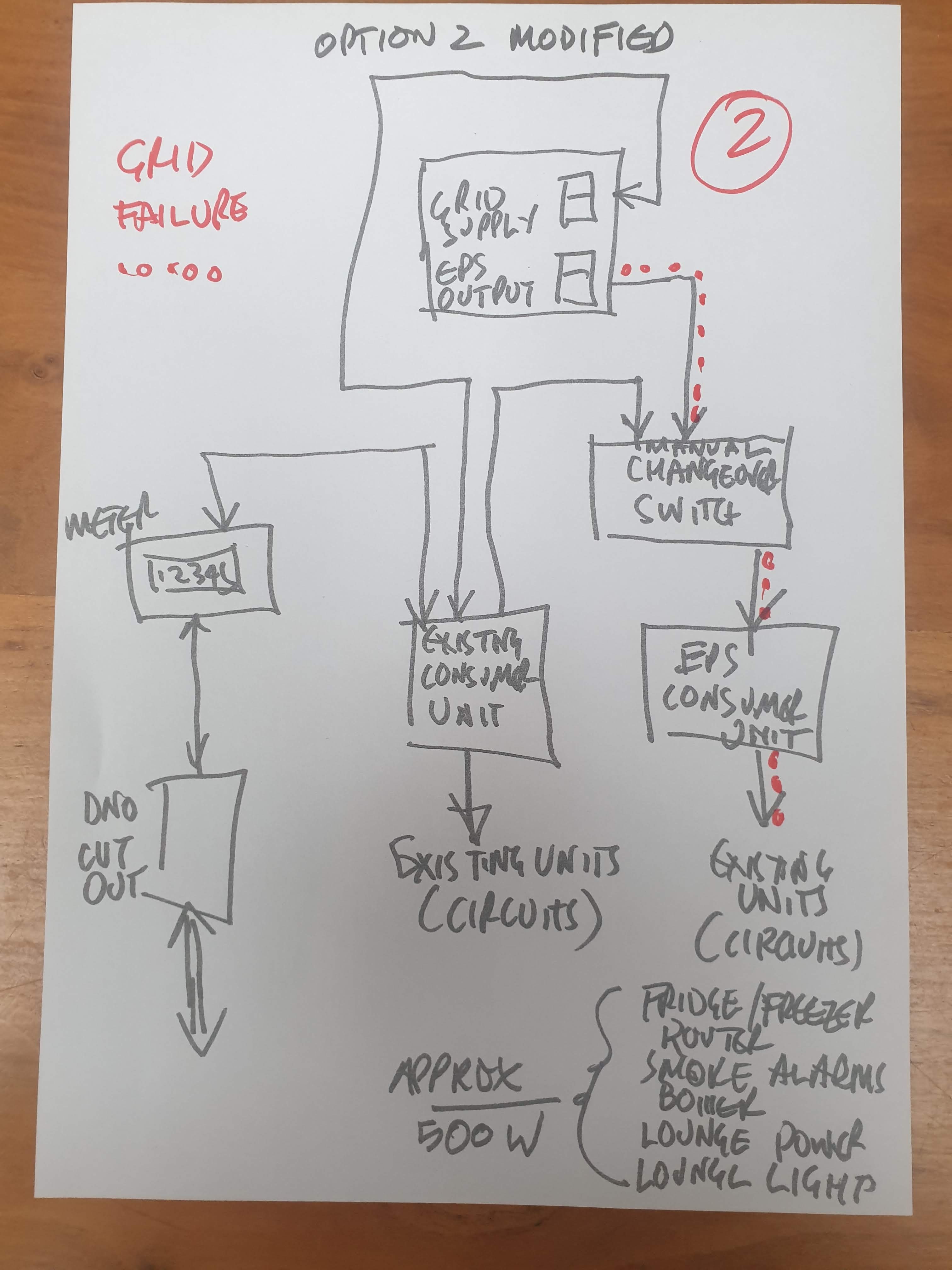
Mine works exactly as my description and drawing
Z
#8ZmGahH6yQBe
SteveCook Mine works exactly as my description and drawing
Your drawing has a manual changeover switch though doesn't it? I'm wanting an automatic switch over in a power cut. Option 2 in the EPS documentation.
#9Slinger
I have a Hybrid 2 inverter and a Dc coupled battery it works exactly as Steve lays it out. EPS relay fitted as standard in inverter, handles Grid outage change over to Battery isolating grid from battery. EPS load is limited to 20A approx 3.5 kw output mine runs the downstairs lighting circuit + Gas boiler power requirements. With a spare dedicated socket for router. Not sure where your installer is going.
Z
#10ZmGahH6yQBe
Slinger Thanks for the info, so you don't have any kind of auto changeover switch installed on your system?
S
#11SteveCook
Yes
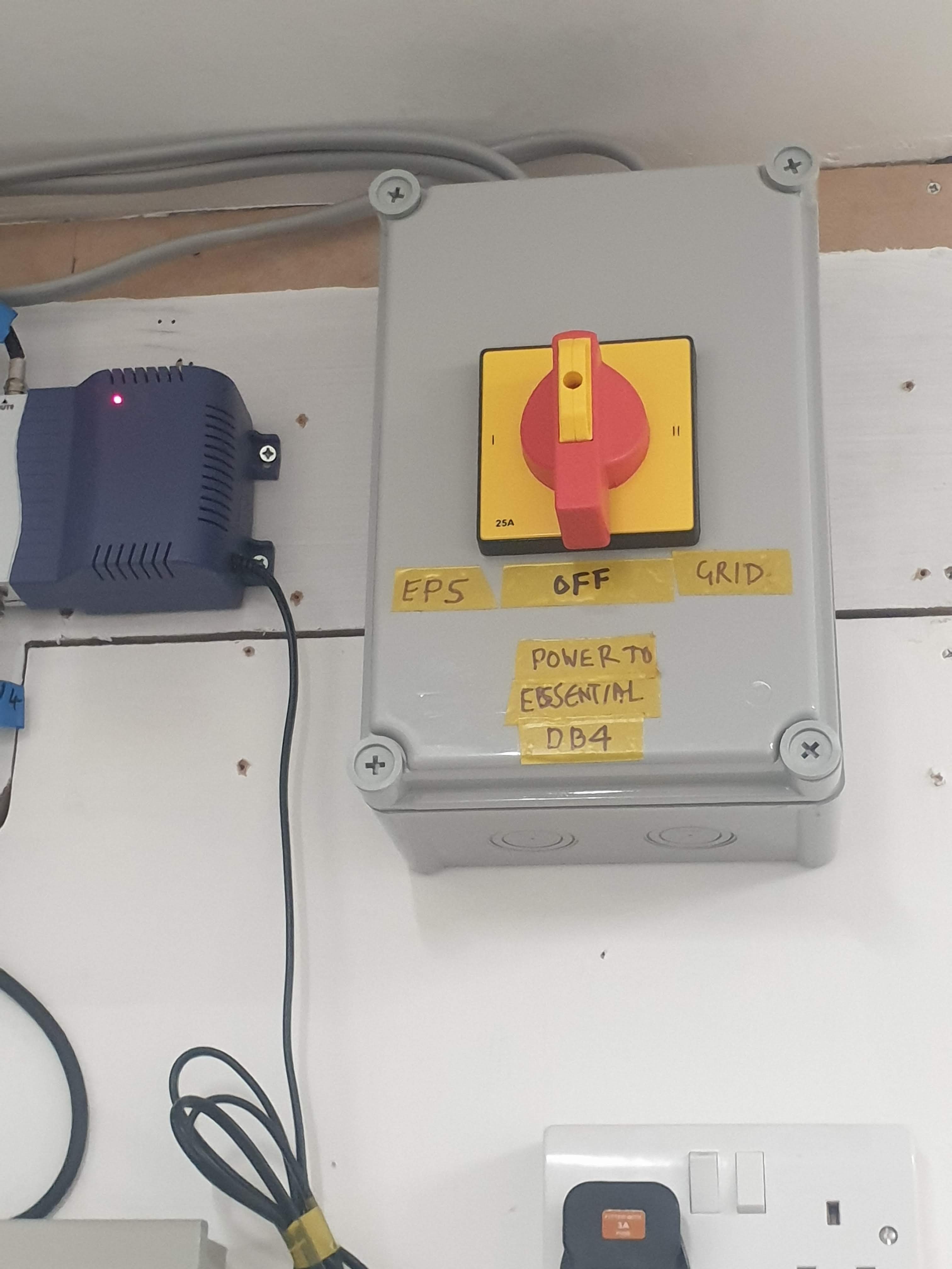
My CO switch is set to EPS in normal operation as the EPS output from the inverter is always live.
When grid fails/power cut the inverter goes to islanding mode and disconnects the grid side for upstream back feed protection to any electricity workers.
The EPS side goes off for about 5 seconds and then automatically comes back on powering the essential DB. GE can apparently change this remotely so there is no interruption.
The CO switch is so I can feed the essential DB from grid if I need to take inverter offline for maintenance.
Z
#12ZmGahH6yQBe
SteveCook I see, that makes sense. It was confusing me on the diagram. So essentially if you remove the CO and it's cable to the "house DB" from your diagram it would still work in the same way, other than you would have no ability to power the EPS circuits directly form the mains supply?
S
#13SteveCook
ZmGahH6yQBe
The auto changeover is not needed because the hybrid 5.0 gen1 I have does have a G98 disconnection device inside to disconnect it from the grid and prevent back feed during mains power failure.
EPS is always live when inverter is on.
I could do mine as drawn without the manual CO switch and feed from house CU, but if I ever wanted to do any work on the inverter and shut it down, the essential CU would become dead.
The CU allows me to shut off inverter, panels and battery and essential CU be grid fed.
If there was a power cut at that point everything would then be dead
ZmGahH6yQBe
correct.
It ran that way for 5 months until the contractor came back and fitted the CO switch
and the cable to house DB.
CO in off position as I was mucking about
T
#15TX200
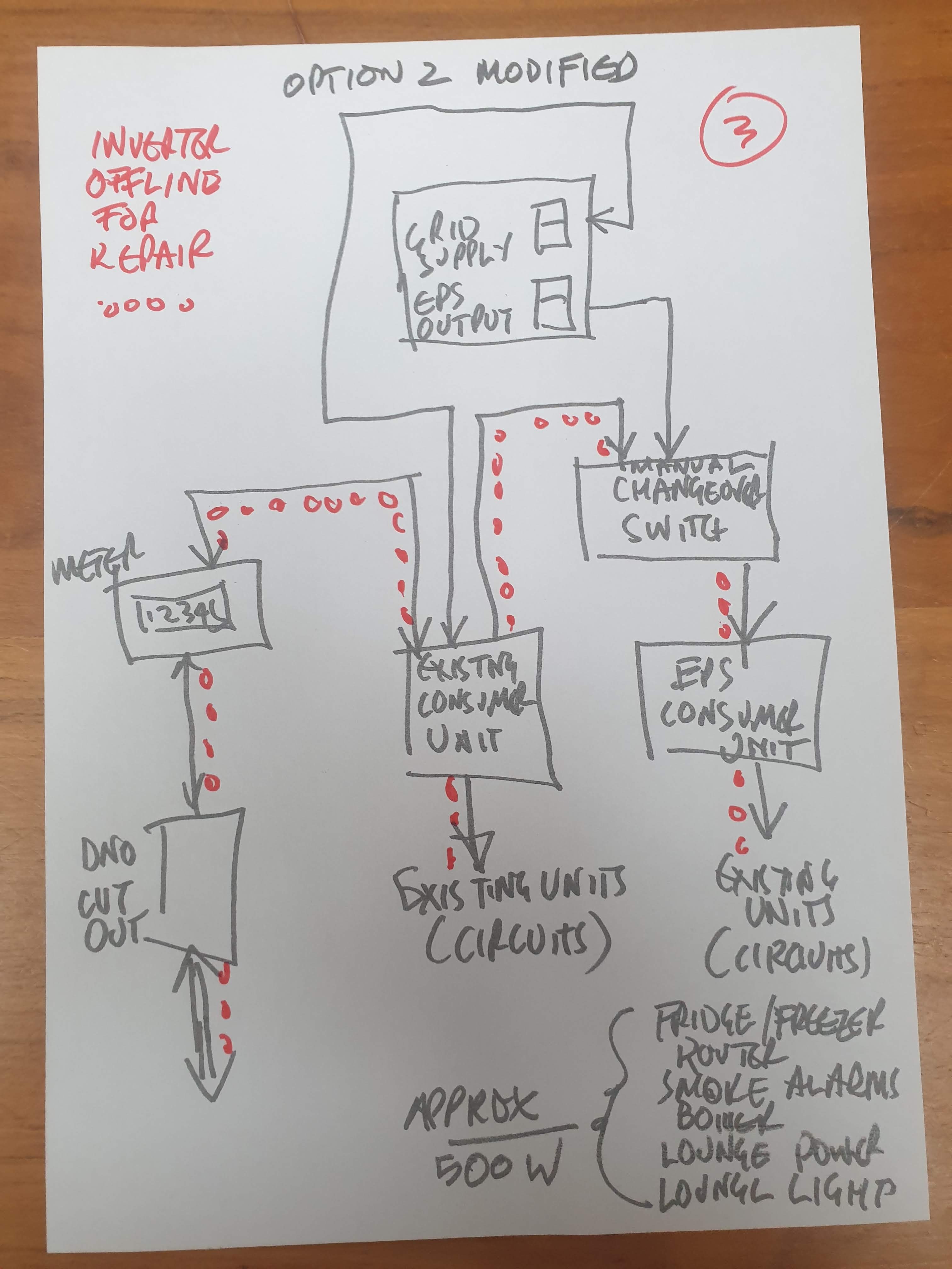
Plus if the inverter ever failed (let's hope not!), Hence why the manual changeover is very useful!
Not sure how long it'd take to get an engineer out to fix the inverter, but could be quite some time without your essential circuits!
S
#16SteveCook
TX200
Exactly.
Hopefully I never have to switch the CO to grid, but option is there
Z
#17ZmGahH6yQBe
So I've been talking to GE via email over the last few days and they have been saying I do need an auto changeover switch, but never explained why. As I was going back and forth with them I asked what the difference between method 1 and 2 in the documentation was then if I wanted a method 2 setup but there is no auto changeover switch shown or mentioned for that method. They then came back saying:
No method 2 on the documentation does not require a changeover switch, it is essentially the same as the socket method but supplies a sub board that goes directly to the circuits themselves.
If the EPS is supplying the main distribution board a change over switch (either manual or automatic) would be required and the inverter would need to be supplied from a sub board.
However my installer has just been on the phone to GE and they have said an auto changeover switch is required for my setup. It feels like GE don't actually know themselves, or are giving out conflicting information on what the setup needs to be.
So I'm getting an auto changeover switch installed when they come back, who knows if it's actually required or not. Personally I can't see what it does in the setup as it appears to duplicate the functionality already provided by the inverter, all be it in a different way.
I guess the sub board will be powered by the mains connected circuit during normal operation, then during a power cut would auto switch over to be powered by the EPS output of the inverter. Rather than being powered by the EPS output on the inverter all of the time. Maybe they are worried about the load potentially being too great for the EPS output as potentially we could plug in some power hungry devices into a socket connected to the EPS. Obviously this is all hypothetical as I don't actually know how they are going to wire things up until they come and actually do it.
A
#18athresuk
There is no mandatory need to fit a changeover switch for method 2 as the EPS terminals are connected to the AC power terminals (via a relay) inside the inverter,
In the event of a grid failure the internal relay will disconnect the EPS terminals from the AC feed and the EPS terminals will be powered by the inverter only.
Obviously the loads connected to the EPS terminals/Consumer Unit should be size to not exceed the inverter output power.
However, if the inverter ever fails or needs to be disconnected then unless the EPS cable is linked to the AC grid supply then there is no longer any power for the EPS Consumer unit.
In this case a change over switch can be fitted to allow the grid supply to be fed to the EPS Consumer Unit incase the inverter is disconnected, this does need to be a correctly wire change-over switch to prevent back feeding the EPS terminals.
So yes, a method 2 EPS install can have change-over switch but is not mandatory.
I have an install which uses method 2, so essential circuits connected to the load which need back-up power all via a separate Consumer Unit and a change-over incase the inverter needs to be removed.
S
#19SteveCook
ZmGahH6yQBe
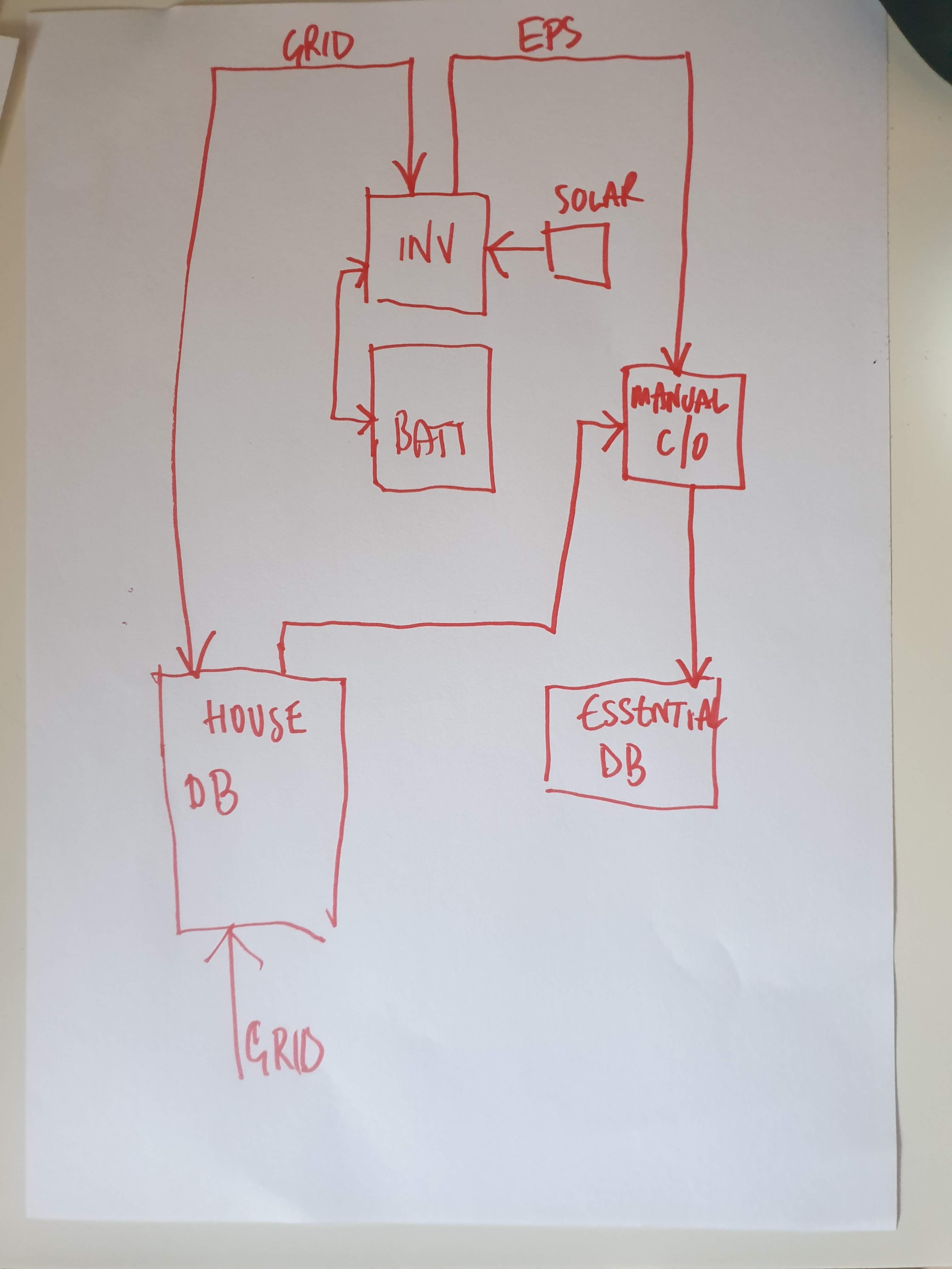
Please see my sketch schematic above that I have for 14 panels, 9.5kWhr battery and hybrid 5.0 Gen1.
No auto changeover because nothing needs to auto changeover.
Manual changeover switch just for maintenance to feed essential CU from grid to take inverter off line.
System ran for 6 months without the manual changeover switch even fitted
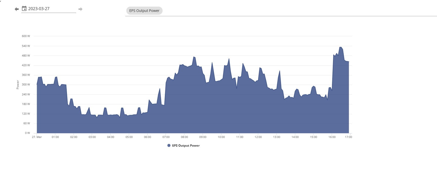
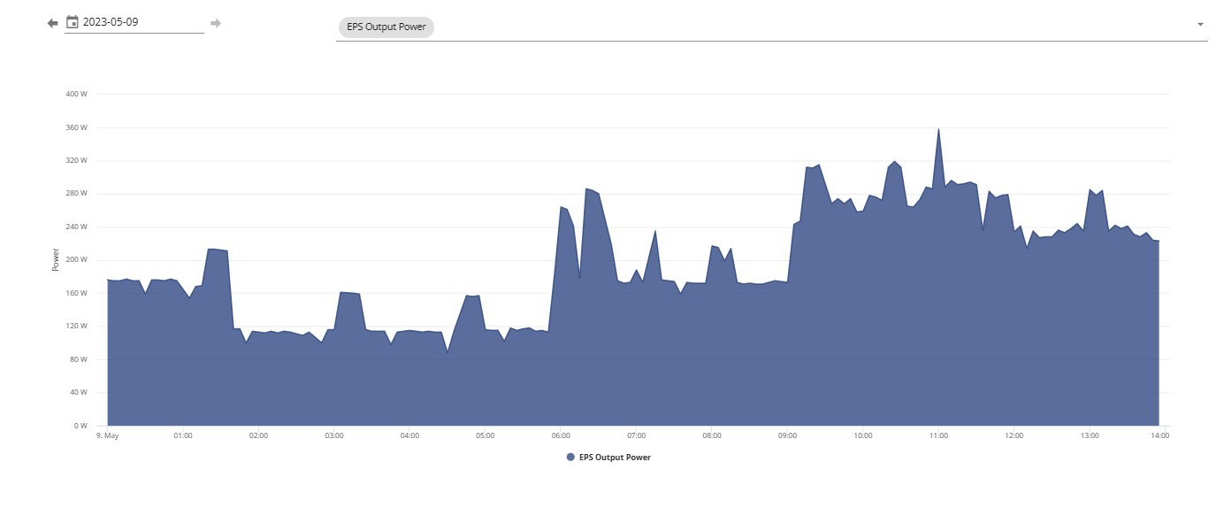
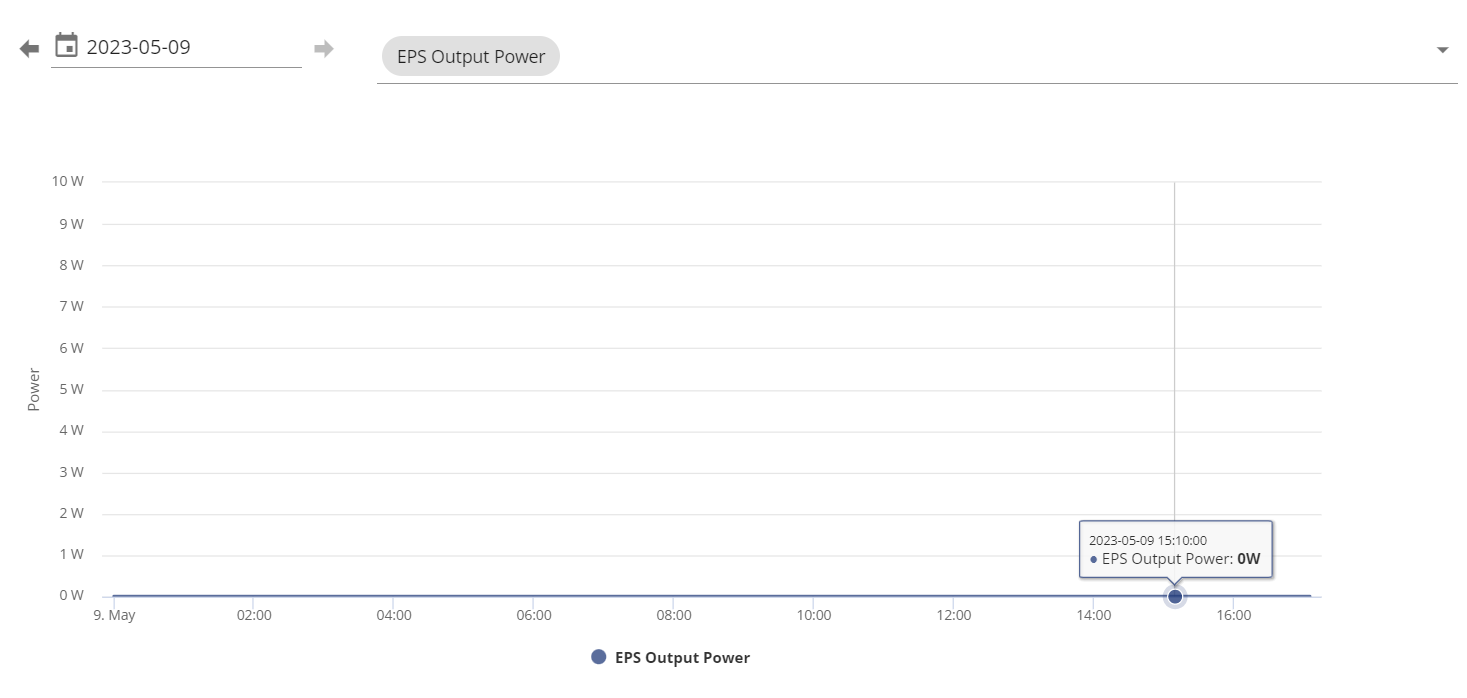
My EPS runs all the time at the same time as the main output to the rest of the house. See graph
The EPS feeds an Essential Consumer unit (CU) which feeds a number of circuits that have a power draw much less than the EPS output. Smoke alarms, burglar alarm, fridge and freezer sockets, router, lounge power (TV and Sky Box) lounge lights and gas boiler controls. In the event of a grid failure we can sit in the warm lounge and watch TV.
On mains fail, everything goes off and 5 seconds later the EPS comes back live. (AFAIK GE can make this no break if you require)
This all works 'cos I have tested it a few times.
Z
#20ZmGahH6yQBe
SteveCook I sent the installer your diagram, and the reply I'd got from GE. But they spoke to GE themselves and they said they need an auto changeover switch so there is not much I can do. If I insist they don't install one and there are issues they will blame it on that. It's not costing me any more, I'll just had to put up with and extra ugly box in the hallway.
S
#21SteveCook
ZmGahH6yQBe
Thanks
Mine is effectively option 2 but with the ability for the essential circuits of the house be switched to grid and go on running on grid if the inverter ever fails
#22Maxwell
Looks like at commision time the installer selects how the EPS will be used. So, does that slection determine whether the EPS is on all the time and what happens in the event of a power cut ? I know on my gen2 3.6 the EPS output routinely shows 0. We haven't got the EPS set up yet.
I wonder why the inverter AC outputs aren't overload protected ? And is it surprising that there is a shortage of lower cost auto switch over options out there. Although perhaps something that has more traditionally been seen in large commercial/industrial settings where 3ph is more common. Are the differences in operation/configuration between invertor manufacturers such that a relatively simple switchover one size fits all solution isn’t viable ?
Z
#23ZmGahH6yQBe
Maxwell I wonder why the inverter AC outputs aren't overload protected
They are overload protected, but it does mention in the documentation that if the overload protection is tripped too many times it can cause permanent damage to the inverter. So I guess you don't want to be doing it if possible.
S
#24SteveCook
Maxwell
We just plugged it in and it works, all that has to be done is the installer "tells" the setup page how EPS has been configured so GE have some sort of record.
If you don't have anything connected and drawing from the EPS, then the graph will show output=zero
T
#25Tim
ZmGahH6yQBe they spoke to GE themselves and they said they need an auto changeover switch so there is not much I can do
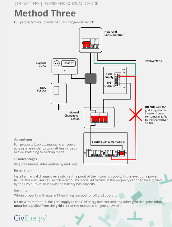
From the first post you put on here, you are wanting to feed a sub-consumer unit with some of the house circuits in. That would require the method 3 installation in the KB article. It's only if you're wanting to feed the whole house consumer unit from EPS that an auto change-over switch would be required (method 4).
It would be useful to know why Givenergy believe that a sub consumer-unit would require an auto-changeover switch if that is still the specification that the installer is working to. Otherwise a manual changeover that is never operated other than during inverter maintenance would seem to fit the bill.
S
#26SteveCook
In an effort to simplify things.
Note isolators etc omitted for clarity.
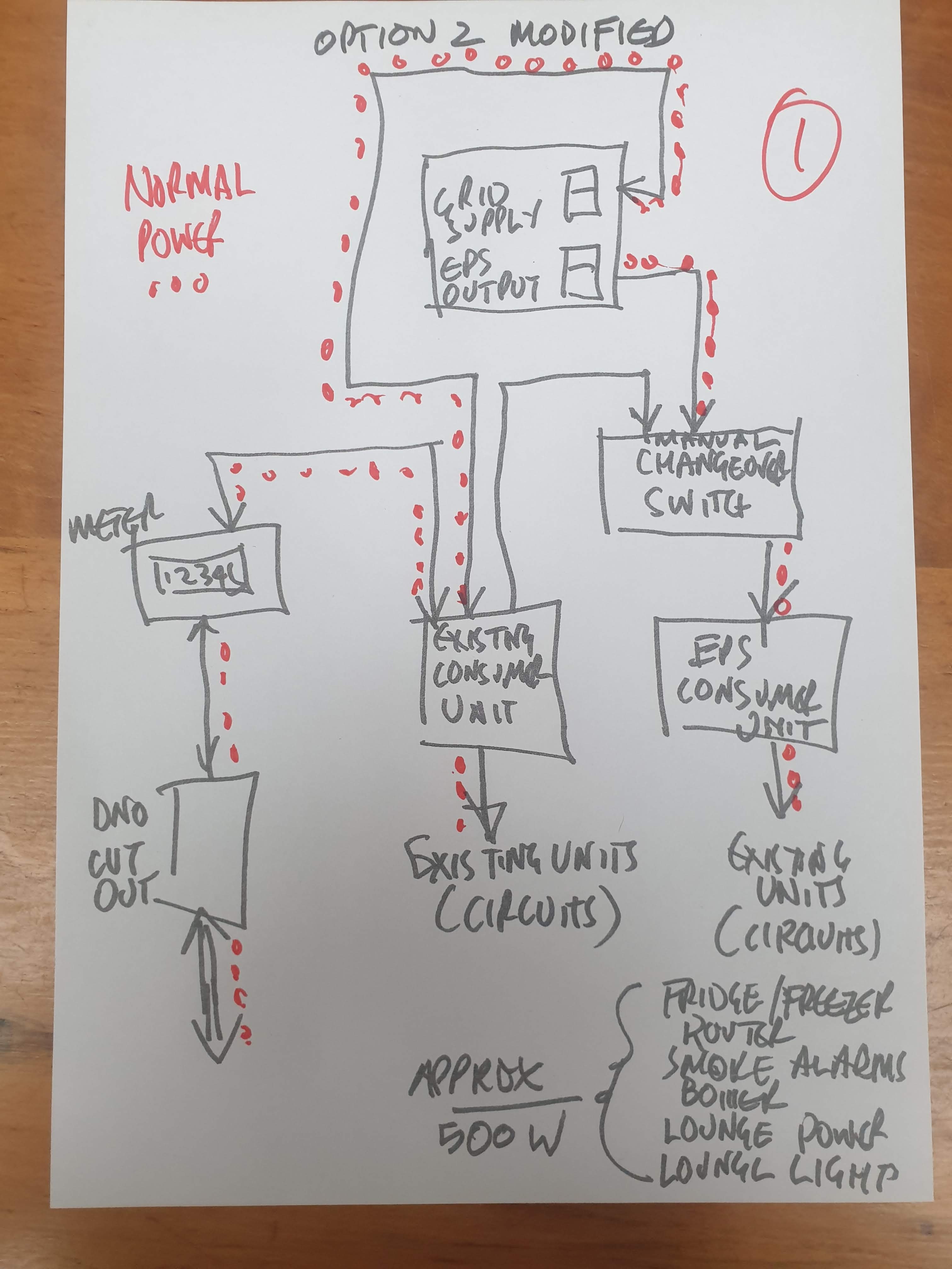
Option 2 - simplified/modified
The GE drawings have a "new grid consumer unit" with connections to multiple inverters. I only have a single inverter so do not need the CU (consumer unit) as my existing consumer unit feeds my single inverter .
#27Maxwell
It would be so much simpler if the smart meter fitted to the house simply blocked any outgoing lecky in the evebnt of a power cut. After all the lecky compnay can remotely switch off the incoming supply to the house and that is done in the meter.
T
#28Tim
Maxwell That would be a very simple interlock to incorporate into smart meters; 240V relay coil across grid L and N operating a DP switch to connect the meter to the grid. But that would not help the situation where the inverter is sited in premises without such a smart meter. The regulations would still want the power source to disconnect itself from grid.
#29Maxwell
Tim So, simple. Give the consumer the choice. Fit a smart meter with this capability built in and no need for the additional faf of adding additional capability consumer side. Or regulate such that you want renewables that connect to the grid then you need one of these smart meters.
P
#30paulwindy
SteveCook Is this not Option 3 and if so the inverter cannot be fed from the consumer unit need to come from the grid side
S
#31SteveCook
If you look at the red line on the drawing above and note that the EPS is always live.
If the manual changeover switch was set to feed the existing consumer unit from the EPS output, it would go back up the red line into the grid supply connection and could then go back into the grid ( and I have no idea what it could do to itself if feeding itself).
If you look at mine there is no way that can happen.
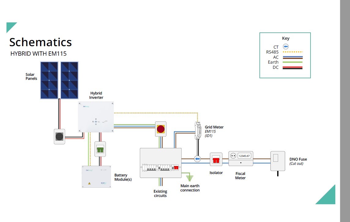
I suspect most installers just feed the inverter of a spare way in the existing consumer unit and do not install whet GE label as New Grid Consumer Unit. This is how both Solar Edge and GE did mine off 2 different consumer units and is shown in the GE drawing from their installation manual.
So I have the EPS output feeding an Essential Consumer Unit
The changeover switch I have means I can feed the ECU from either EPS (permanently live) or mains (if I want to take the inverter out of circuit)
By using the CO switch the 2 can never cross connect.
Mine is essentially 2 modified and omits the New Grid Consumer Unit
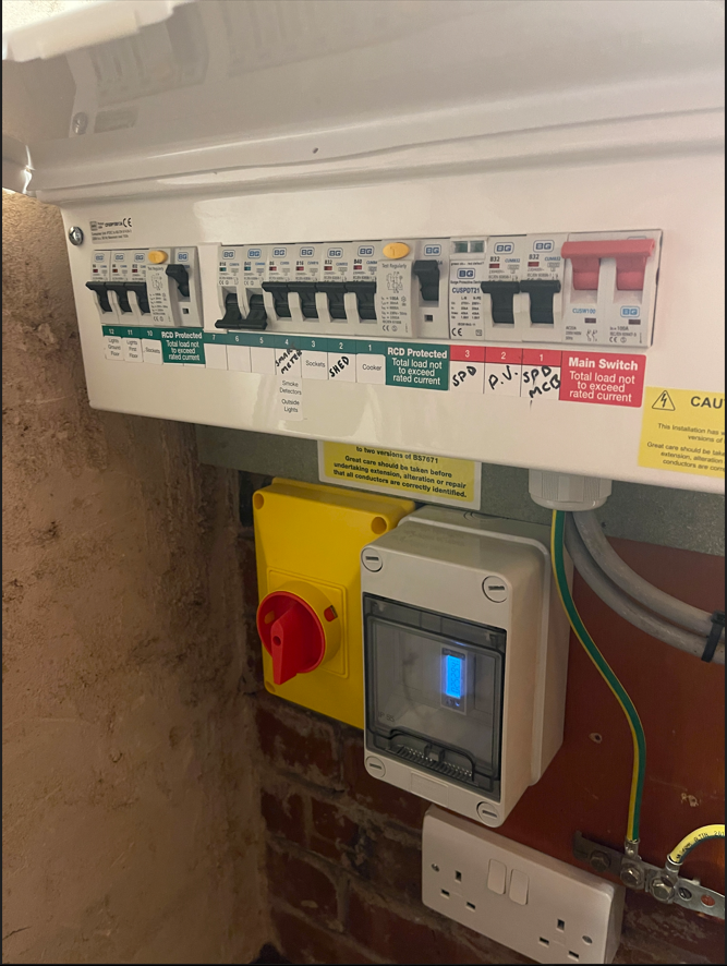
On looking at your sketches again think this is how mine has been done, just need to check with installer that the isolation switch is foe the inverter / grid so the inverter can be isolated but the circuits supplied by the EPS can still be feed if the inverter is isolated.
Mine has all been done in one consumer unit (split consumer unit) think the switch next to the meter is the change over from EPS to grid for the essential circuits
S
#33SteveCook
It looks like your inverter is fed (feeds) from a spare way on the existing consumer unit (as i suspect most electricians will do it this way and it matches the GE schematic above).
Not sure what the big changeover switch is doing and which section of the split board it feeds - don't want to overload the output capacity of the EPS circuits in the inverter.
I guess it must feed the LHS, as circuit 1 RHS is cooker and that could be a problem if EPS was feeding that?
Is your EPS permanently live?
S
#34SteveCook
It may be that they have wired it so the changeover when in it's normal position is main fed (not EPS fed) and when mains fails the grid goes off, and everything goes dead.
You then open any breakers that are not essential and high load - eg cooker and then flick the changeover switch to the EPS output.
If it as described above, your EPS output graph will be zero.
#35Hook
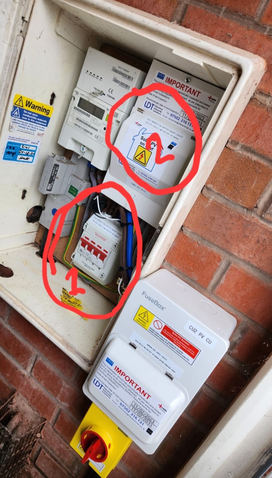
Yes Method 3 which is the manual option should definitely have a zero on the EPS output graph. On mine below, Switch 1 turns off power from the grid, which puts the inverter into EPS mode. Switch 2 sends the power from the EPS to the house.
T
#36TX200
paulwindy worrying that the big red switch isn't labelled. Should be, so it's obvious to anyone what it does!
T
#37TX200
Hook is there a chance the DNO would complain about all that extra kit in their meter box? 😁
Nice neat job though. Everything is labelled, so as to be obvious. And the DNO returned the G98 in 16 minutes which must be some kind of record, so he’s doing something right.
I picked my installer based on locality to me and reviews, so I knew what to expect.
P
#39paulwindy
TX200 I guess it will be once complete, still waiting for the roofer to turn up and fit the panels so the system has not been commissioned yet
P
#40paulwindy
SteveCook Yes it is the LHS that is the EPS fed, I guess the EPS is live and feeds the circuits but as its not been commissioned yet I cannot get on the inverter to see yet