Meter comms failures

14 comments started 2023-04-08 last 2023-04-09
GivEnergy ProductsAC Coupled
G
#1 Giant

Hi. Am seeing a least once a day an error in the log relating to meter comms fail. Up to now it doesn't seem to have caused any issues I've noticed.

However yesterday the inverter went to WARNING and stopped working and that coincided with a meter comms failure message.

This prompted me to look closer at the logs and I noticed some entries where my inverter has been restarted with the message "Automated Maintenance - Plant Meter Comms Fail"

Is this something being initiated server side by Givenergy?

Second question... Do I need to get my installer back, or is this a known issue with a plant setup? I only ask this due to the automated restart and message I put above suggests its perhaps a known issue?
T
#2 TX200

Probably worth getting your installer back, or maybe do a web chat with GivEnergy support.

How is your EM115 energy meter connected to the incoming mains CT clamp, is it wired or radio (LORA)?

Guess it could be interference? Guess unlikely to be a loose connection if it happens so often and corrects itself quickly?

Presumably you have multiple EM115s one for each inverter?

T
#3 Tim

TX200 @Giant will only need an EM115 for each inverter if they are installed as separate devices. If they've been installed as a plant where one inverter is master with the other slave, over the Modbus, then a single EM115 will do, since he has no separate PV inverter. The comms fail could be the EM115 is faulty, or more likely, the connection (STP or LORA) as you suggest needs checking.

G
#4 Giant

Thanks for the replies. The ct is wired to the (single) em115 by the looks of it. Then a long run of a different kind of cable (cat5?) to my garage where the inverters are.

I'm trying to upload photos but the forum is throwing an error. I guess I might need to resize them smaller.

G
#5 Giant


T
#6 Tim

Giant There's another thread where the installer used cat5/6 cable but didn't use a single pair. They used one pair for one core and another pair for the other core. Especially over long lengths, the quality of the data signal really benefits from using a twisted pair to negate electrical interference. That said, the terminations can also be loose and finally, the connector at the inverter end can sometimes work loose. The installer can check all these for you if you don't have the confidence to check yourself.

G
#7 Giant

Just to confirm... the "Automated Maintenance - Plant Meter Comms Fail" where the inverter is being automatically rebooted, is this Givenergy doing this?

S
#8 SteveCook

The black and white cables send electricity input/output from the clamp to the EM115.
The EM115 then needs to send that data to the inverter

where/what are those cables

G
#10 Giant

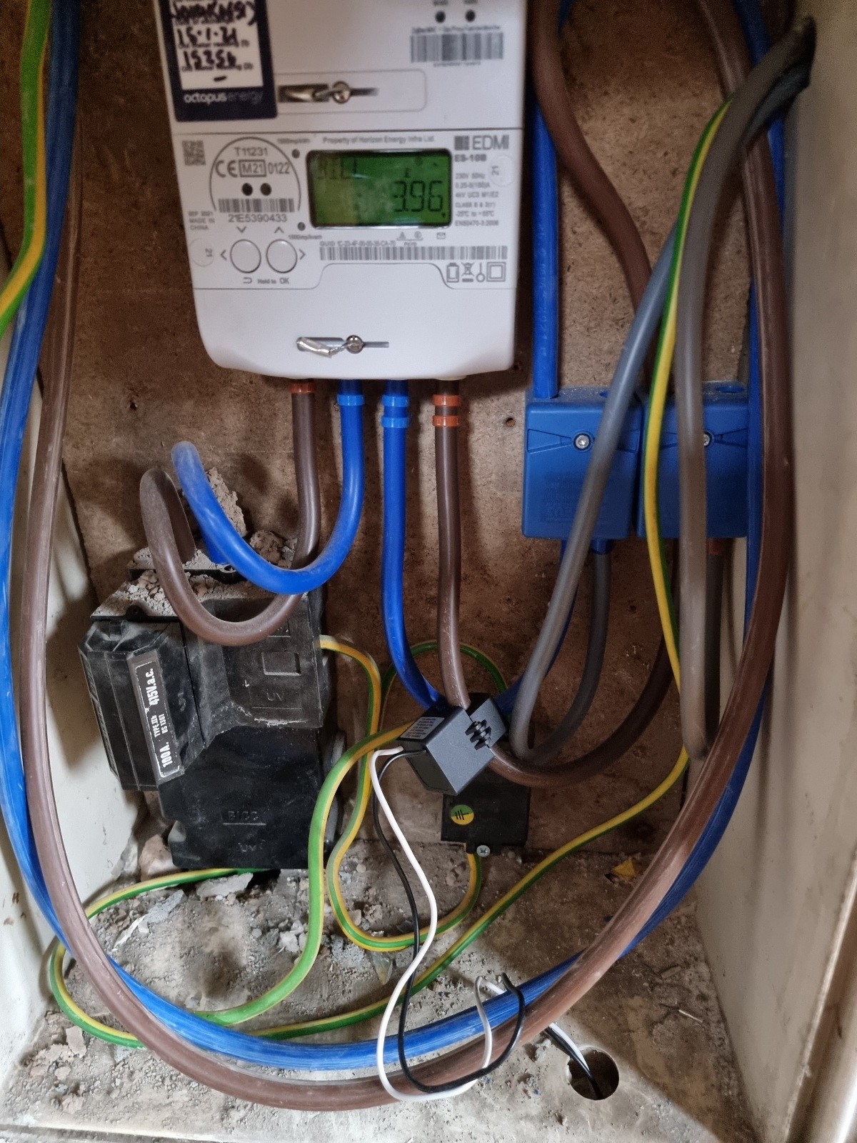
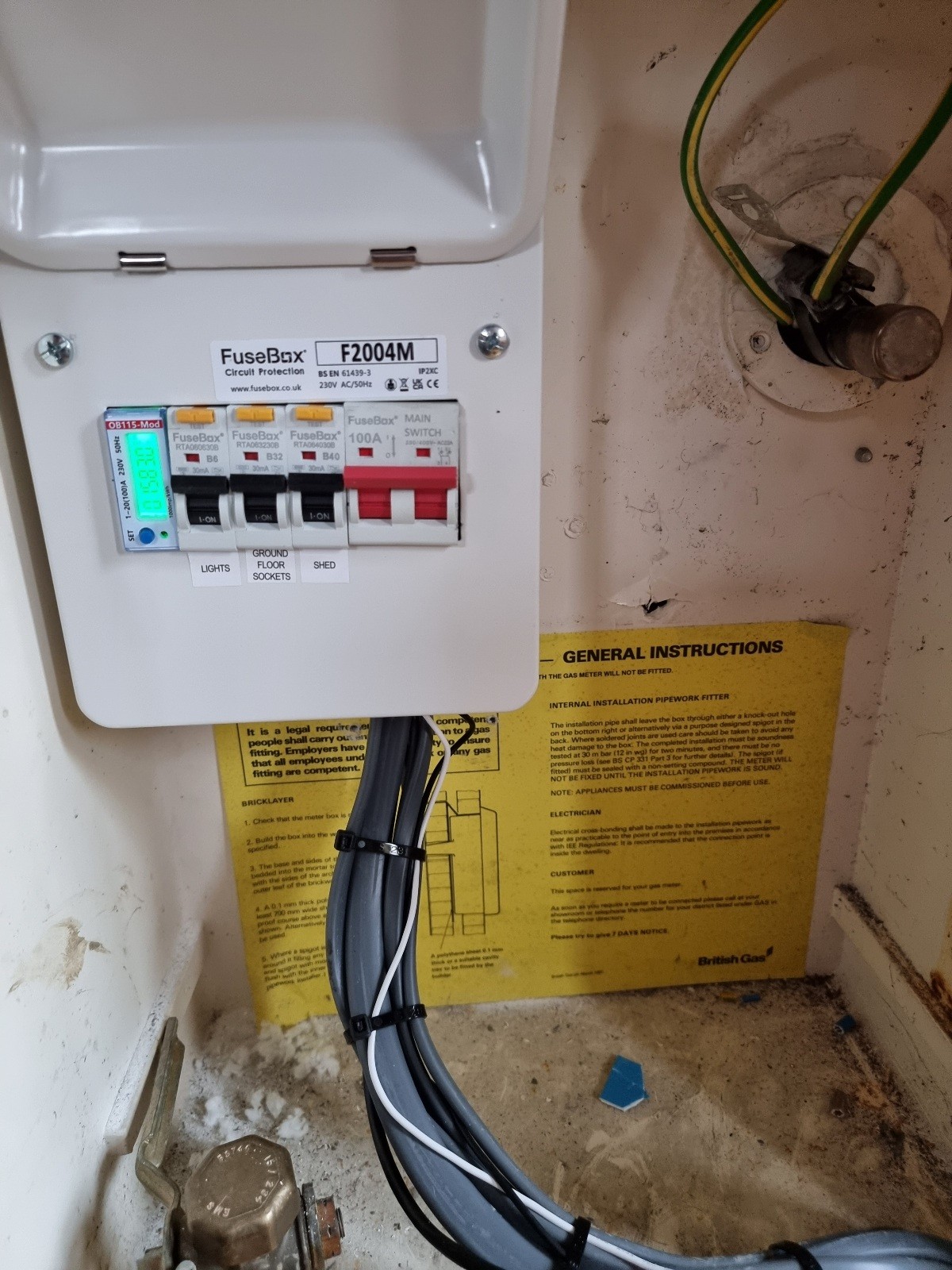
The cable going to the inverter(s) is the single black cable mixed in amongst the grey ones.

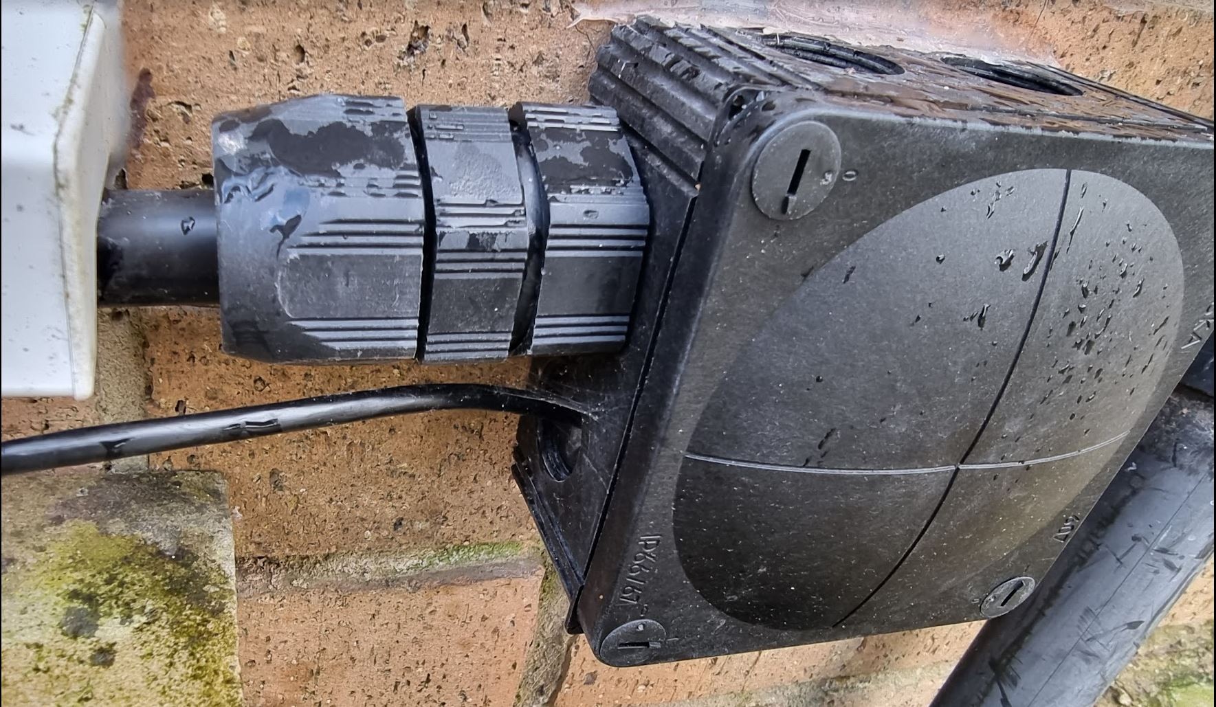
Difficult to see amongst the mass of grey ones, but here it is coming out of that cu, through an external wall into a junction box. Then from the junction box it follows the armoured cable to the inverters.

S
#11 SteveCook

take a pic of your EM115if you can and are happy/safe
supposed to be single cores of a data cable pair. NOT like this OR a NOT bit of twin core flex!

G
#12 Giant

Not sure I'm comfortable taking the front off the cu to be honest. More cos I don't want the installer having any reason to blame me for any issue.

I've seen comments on the Facebook group stating that these errors are 'known issues' with a plant setup. Is that true?

T
#13 Tim

Giant I think this black cable is a UV-resistant cat 5 cable.

No issues with removing the consumer unit cover. Your installer should respond and send someone round to check:

  • Modbus connection is made by connecting a twisted pair (eg Blue and White/Blue) to the A+ and B- terminals;

  • the connector that plugs into the inverter is terminated correctly.

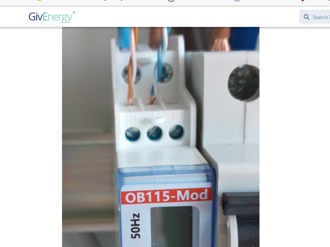
The picture above shows the use of two separate twisted pairs but it is not effective in reducing interference because the A+ and B- terminals are using both wires on a single twisted pair. To work effectively (if two cores per connection are deemed necessary), the solid colours should be on one terminal (eg Blue and Red) and the respective white/banded colour on the other terminal (eg white/blue and white/red). That way there are two twisted pairs each carrying the data signal back to the inverter.

S
#14 Slartibartfast

After re-wiring the whole lot etc. I've come to the conclusion that it's a 'plant' feature. For a 'plant' to use Modbus as a control one inverter has to be Master. There can only be one master. I asked the question - what is the ID of the slave inverter? No reply from Givenergy. I suspect that these comms errors are caused by clashes on the bus - both inverters are trying to be Masters. Could explain why the 'EMS' is needed - RJ45 between the inverters.