
Meter change & CT clamp direction & excessive house load

8 comments started 2023-05-26 last 2023-08-08
GivEnergy ProductsHybrid
G
#1 geoffreycoan

Yesterday Eon came and fitted a new economy 7 (multi-rate) smart meter. Very long story as to why I’ve had 4 different meters over the last year, but at its core Eon can’t upgrade an existing smart meter configuration from single rate to multi-rate.

In the process the engineer tidied up all the wiring in my meter box which was a rats nest of cabling after the heat pump and then solar battery systems were fitted.

In doing all this work he had to disconnect the CT clamps (I have twin AC5 hybrid inverters) and then reconnect them afterwards. He took a picture of them beforehand and used that when he clipped them back on.

After the power was restored we noticed on the GE app that the house was pulling 6-8kW which the panels alone were not able to provide so the batteries drained down through the afternoon to supplement the demand. I thought it odd that it was a sunny day and the batteries were not charging but put it down to things like the heat pump and hot tub restarting themselves. I did check the CT clamps and they appeared to be the right way round.

This morning, same thing. Batteries fully discharged, house demand was running at 8-12kW all the time, panels not generating enough to support the load so pulling in 7kW from the grid and this load started at about 6am this morning.

Very confused as to what is drawing 12kW all the time. Went round turning off circuits to see where the demand was coming from and couldn’t isolate it and stop the current draw.

Re-read the installation manual for the CT clamp direction, and just to see if it made a difference, swapped the CT clamps round. Amazing, the house load dropped to just 2kW and the batteries started charging up.

My summary is that the Eon engineer installled the CT clamps the wrong way round, and because I also have an existing 4kW FIT array (with an existing Growat inverter that isn’t monitored by the GE system), when the FIT array is generating power that the house isn’t using, the CT clamps were recording the FIT export as an import and were draining the batteries to supply this phantom house load.
Swapping the CT clamps round solved the problem.

In diagnosing and fixing the problem I think the GE installation manuals are still not clear about the installation of the CT clamp.

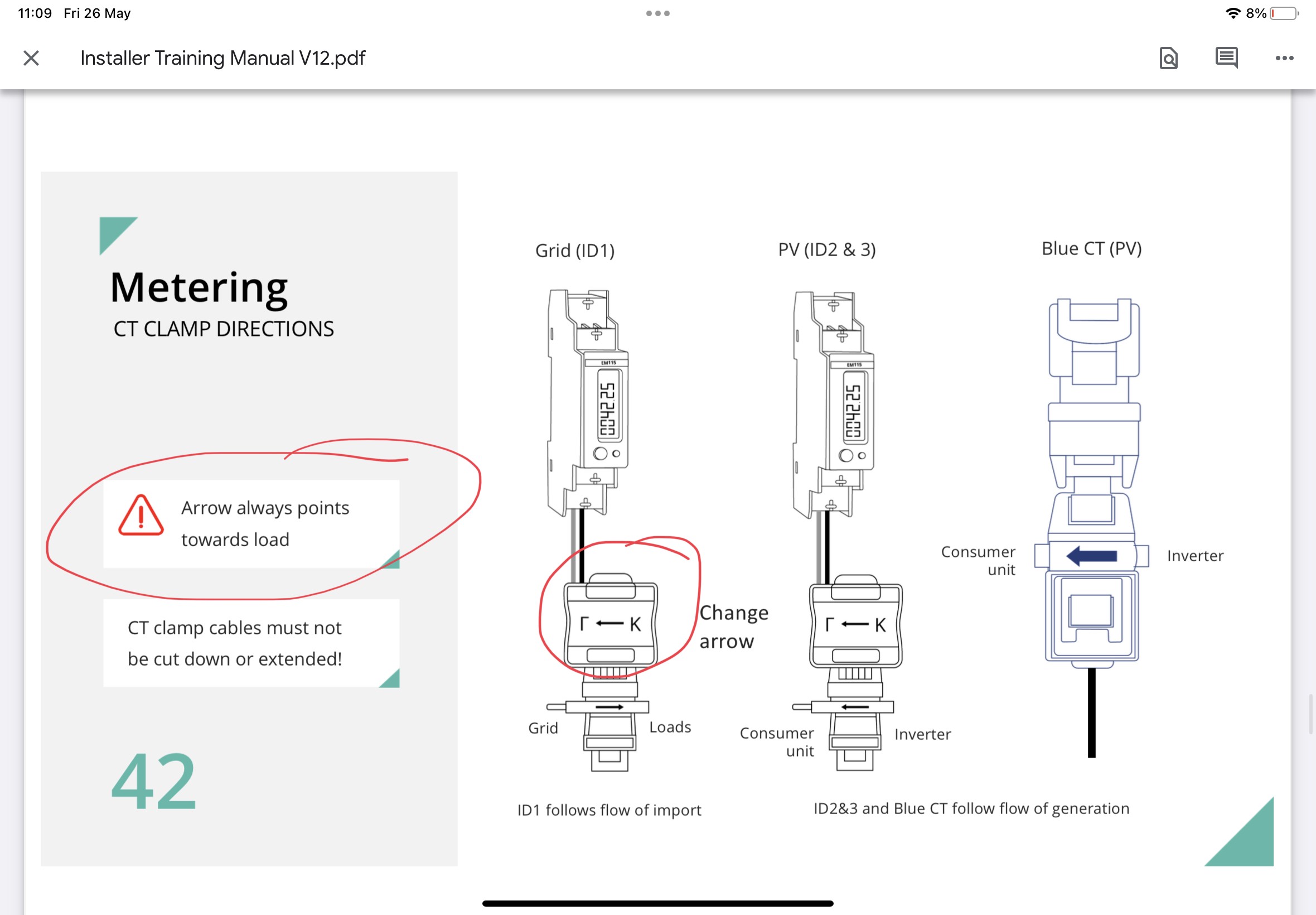
The “installer training manual V12” shows the CT1 arrow pointing towards the grid, the L on the grid side and the K on the load side. But the text says that the arrow should point towards the load.
A previous installation manual “Installation Manual Givenergy All 2021” shows the L on the consumer unit side, K on the grid side and that the arrow should point towards the consumer unit.
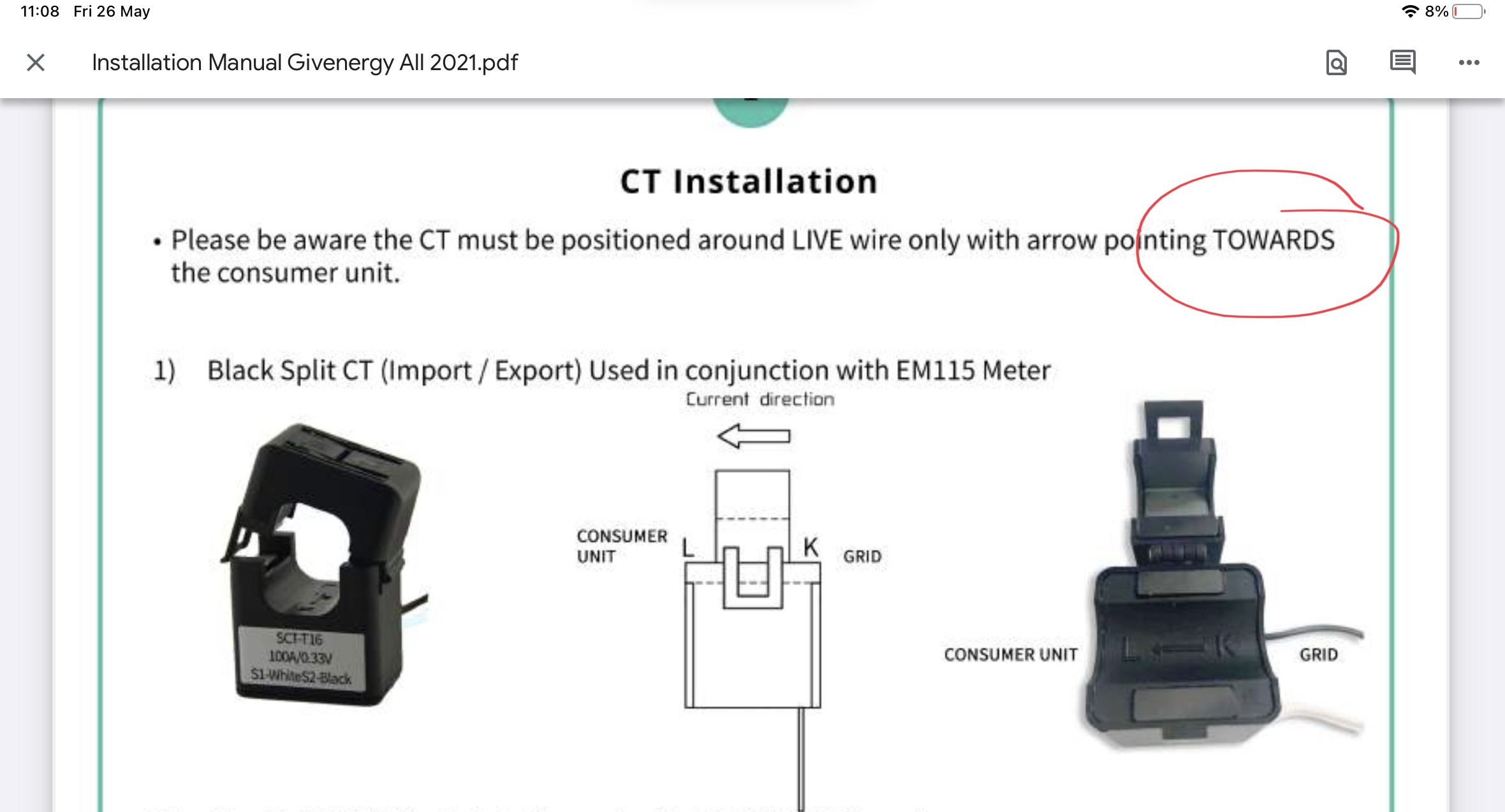
My system is now setup with the second of these, the L on the consumer unit side and the arrow pointing towards the consumer unit and its working fine.

A
#2 agent_paul

geoffreycoan did you get an answer to this? I've had a 2x hybrid system installed recently and I'm currently seeing phantom demand on my system similar to yours (4-6kwh) when nothing high powered is on.

#3 Woodstock

agent_paul Direction of arrow is only half the story. This presupposes that the black and white wires are connected the right way round at the other end. My installer reversed the black and white connections. Measurement works correctly but to achieve this the arrow on the CT clamp is pointing the "wrong" way.

G
#4 geoffreycoan

agent_paul Hi Paul, no I never got any follow-up to this. As I said I think the latest GivEnergy is wrong, or at best unclear. I unclipped the CT clamps and turned them round and the system has been working perfectly now, no phantom demands.

It’s worth saying that the GivEnergy app only gives an instantaneous figure every 10 seconds (local mode) or 5 minutes (remote mode) so if you’d just turned a high demand appliance off then the inverter may still be reporting the demand as being there. In my case I was seeing constant high demand that wasn’t there so I knew something more significant was wrong.

You can swap the CT clamp round yourself, 10 second job, and see if it makes a difference. If you have multiple inverters then maybe one clamp is the wrong way round? On the GE mobile app if you turn on ‘show multiple batteries in the options you can see what each individual inverter is doing on the batteries tab.

I would also look at the inverter notification log on the cloud portal. Are there any errors such as comms failure being reported? This might point to either a faulty CT clamp or the CT clamp wires in the bottom of the inverter not being quite connected right which is giving spurious readings. If so, call your installer back out.

A
#5 agent_paul

Hi geoffreycoan , Woodstock thank you for your quick replies.

My situation is a little odd. The seemed to work (mostly) fine until the recent firmware update. (There were some odd graphs with negative values but that was only sometimes during the afternoon). It only after the update do I have these phantom demands.

In regards to the CT clamps, they both look to be pointing in the right direction (both are on the live wire before the elec meter pointing towards the meter) and in terms of the wiring, I just popped off the cover to have a quick look and both the back and white wires look to be wired correctly, according to the installation manual. I'll try to reverse both the clamps later to see if it changes anything, although I'm a little cautious as it don't want to be messing about with it while it's also being monitored/investigated by the installer.

Looking at the notifications is a good shout. I'll have a look on that too

#6 Woodstock

agent_paul The CT clamps will work fine where you have them but they should really be just after the meter rather than before. The way you have them the power used by the meter is treated as house load because your system is balancing import/export upstream of the meter. This means that power to run the meter will be coming from your solar/batteries (which is a cost to you) rather than from the grid (unmetered) which is not. The amounts involved are relatively small but every little helps. 🙂

A
#7 agent_paul

Just a quick update.

I'd like to thank both Woodstock and geoffreycoan for all the help. After talking to the installer company, they were ok for me to switch off one of the inverters (the one without the battery) in order to investigate and try to get the system in a workable state (while they investigate other options). I did that and the phantom load was still there. I popped off both CT clamps, identified which the one was the one connected to the running inverter and flipped it. Bingo! It's working as it should now. I'm going to leave it for now to get a full day of normal operation before doing the same on the other inverter.

G
#8 geoffreycoan

agent_paul Excellent, pleased we were able to help you find and fix the problem.

One other thing from your message, are you saying that you have two inverters but only 1 battery (connected to one inverter)? That’s very similar to the setup I initially had, two inverters, one battery, and then I had a second battery connected and the installer connected it to the same inverter that already had a battery.

If you have got two hybrid inverters but only batteries on one then my personal experience of that setup is that it is highly likely to result in you getting over-voltage errors on the inverter that doesn’t have the battery connected. I didn’t understand at the time of my multi-inverter installation but the GE inverters are not connected together in any way, and they are ignorant of each other. I found that on sunny days the inverter without batteries is generating more power than the home needs it will be exported, but in doing so it pushes the voltage up, and if your supply voltage is near the 253v limit it will cause the inverter with the batteries to record an over-voltage error and turn itself off to protect itself. I was getting sometimes 10 or more over-voltage errors a day, and each one could last for an hour or more. I first discovered this was happening when I saw the inverter was showing a red light, the battery wasn’t charging and yet it was a lovely sunny day.
Eventually tracked it down to being caused by the inverter with no batteries connected. I got a battery moved onto that inverter so there is one battery on each inverter now, and the volume of errors and inverter trip-outs dropped dramatically. I still get occasional errors on sunny days but they tend to only last 5 minutes at a time now.