ESP circuits. Selectivity (discrimination) between RCDs

10 comments started 2023-12-27 last 2023-12-28
GivEnergy Products
6
#1 666tim666

I have a problem which others may also have seen relating to selectivity when there are multiple RCDs involved. I have a separate 'ESP' CCU which is normally supplied from the ESP output of my inverter. My ESP CCU is populated with 7 of RCBOs (combined MCBs and RCDs in one unit) so that an earth leakage fault on any one ESP circuit causes only that circuit to trip. This selectivity means that in most cases I won't loose power to multiple circuits when a fault occurs. This design is commonly used in consumer units generally and is not just an 'ESP' thing.

The problem arises because there is an RCD on the input to the inverter, and also on the ESP output of the inverter, and so, in the event of an earth leakage error on one of my ESP circuits, then, randomly, any one of the RCDs may trip. They are of standard sensitivity and response time defined by their type which is type AC, 30mA.

So a fault in, for instance, a lighting circuit, could cause loss of power to all lighting circuits, fridge, freezer, boiler, router, and inverter/battery system.

So I want to fit type S RCDs, or no RCDs at all, on the main input to the inverter and the ESP output from the inverter. This would transfer the primary RCD protection back to the RCBOs where I want it. Type S RCDs trip at a higher current and after a longer delay.

I don't know if there are earth leakage trips inside the inverter (type GIV-AC3.0) and how they may behave.

Do people recognise this problem, and have they solved it, and if so how?

D
#3 DD

666tim666 do you need the RCD on the ESP output, since all the downstream circuits are already protected?

6
#4 666tim666

SteveCook Steve, we may be talking about different things. Yes, its been raining here a lot, but that is not the problem. The problem is selectivity (discrimination) between RCDs when there is a row of them on the supply to any one particular final circuit. That is why I want less sensivity on upstream RCDs.

6
#5 666tim666

DD Yes, your comment is valid. My installer wanted to fit an RCD on the ESP output adjacent to the inverter because it is in the garage and the ESP CCU board is in the house. So there is a fairly long sub-main cable. However, it is 10mm2 armoured and so it doesn't present much of a risk to life or anything else. I think I could persuade him to remove that RCD altogether and fit an MCB instead.

That does fix the problem of the RCD on the input to the inverter.

S
#7 SteveCook

666tim666
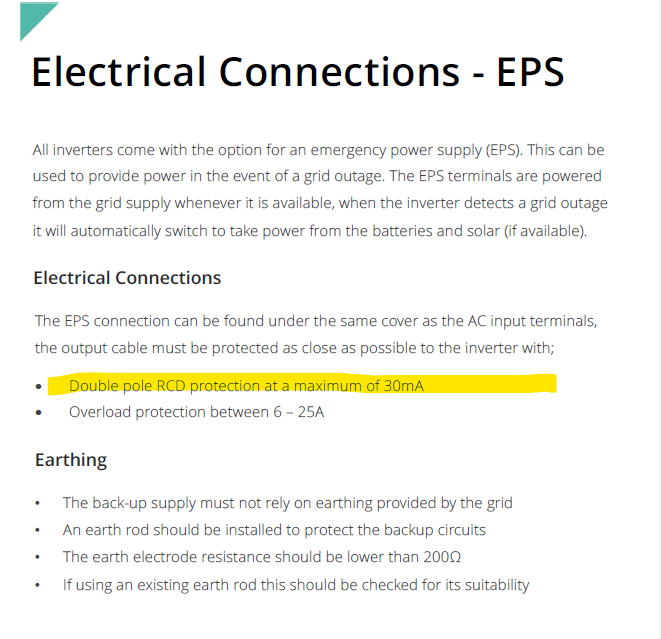
GivEnergy installer guide V12

6
#8 666tim666

SteveCook Thank you, Steve, for that information. It is definitive and quite clear and so there is no point in my chasing my installer in order to change the RCD on the ESP output when he is just following the instructions that came with the system.

Is the installer guide available for us to read or is it only offered to installers?

6
#9 666tim666

hoggy Thank you for that. The document indicates that connecting the inverter to the grid through a 30mA RCD is not the preferred installation option and that, if an RCD is required, it should be a less sensitive 100mA type.

I take it that the default choice is to connect inverters to the grid without an RCD but that if the connecting cable(s) pass through a place or is/are fitted in a manner which warrants protection then a 100mA type should be used.

Your link directed me to a place where I can download the installation manual - I have not found that before. It says that if an RCD is used on the grid input to the inverter then it must be dedicated to the inverter and not shared with other circuits. And that a minimum of 2.5mm2 cable is required. Hmmm.