Installing 2 Hybrid Gen3 GivEnergy Inverters

25 comments started 2024-07-01 last 2024-07-02
GivEnergy ProductsHybridBattery
A
#1 AndrewH

Hello Community. We have a very large ground mount system that requires 2 Gen3 inverters, the supply type is single phase. How do we connect these so that the management of these is controlled effectively. E.g Master, Slave. Leader Follower? Also with regards to the ID1 meter do we have to install 2 of these or will one be sufficient and how will this be wired across the 2 inverters? There will also be 2 x 9.5kwh connected either one to each inverter or both on one inverter.

We have managed this simply with other brands but can't find any documentation with relation to GivEnergy.

We would use another brand but our customer is keen to use GivEnergy

V
#2 Vestas

Multiple inverters with batteries isn't officially supported by GE which is why you can't find any documentation. Some people have it working and allegedly GE are working on some sort of management system for multiple inverters/batteries but I wouldn't hold your breath on that happening, been ongoing for years now.

Were I you I'd pick a different manufacturer. Edit - bear in mind you (as installers) will be 100% responsible for getting things to work and ensuring they stay working for the lifespan of the system.

G
#3 geoffreycoan

AndrewH Andrew, it’s very simple, you just install the inverters as normal each with their own CT clamp, and meter as two parallel systems. There is no interconnect between the inverters, there is no concept of master/slave with the GivEnergy inverters.

I have had this setup for over a year (albeit with Gen 1 hybrids) on a total of 10.4kW of panels and it works fairly well.

A few points to highlight:

  • if you look in the GivEnergy inverter FAQ’s, this ‘plant’ configuration is not recommended. It does however work, both inverters will share the house load between them. You get the benefit of 2x the inverter charge & discharge rate
  • as the two inverters are independent of each other they can cross charge, especially at night when one battery discharges to meet house load and the other sees the excess load and starts charging. You can prevent this by setting a battery pause (to pause charging), but have to cancel that in the morning
  • the consumption statistics and graphs in the GivEnergy app and portal are “limited”. I get negative consumption figures for example
  • in my experience you MUST spread the batteries across the inverters and don’t load them on one inverter. For a start you’ll be limited by the charge/discharge rate of just one inverter, but moreover, the inverter with no batteries will have to export all excess solar, which can cause the inverter with the batteries to trip out with high grid voltages. This is what my installer did

There is a CEMS unit coming from GivEnergy that will provide the sort of interconnect that you might expect across multiple inverters. Release date unknown and I believe they are focussing on multiple AC coupled systems first not hybrid.

GivEnergy have just announced availability of multiple AIO systems, up to 3 can now be connected in parallel so this might be another option.

D
#4 DD

geoffreycoan you just install the inverters as normal each with their own CT clamp

I wonder if you can play games with CT clamp placement, so that one sees more than the other. Then one is nominal master. It may be that this way, cross-charging will tend to happen in only direction, and therefore easier to mitigate?

You can prevent this by setting a battery pause (to pause charging), but have to cancel that in the morning

Wouldn't cancellation be automatic, given that pausing is based on a timer?

G
#5 geoffreycoan

DD Physically there is always going to be one CT clamp installed just ahead of the other on the meter tail. Whether you could do something more clever with boards and sub-boards and clamps in different positions across the boards, I don’t know.

But the cross charging I see is always from inverter 1 discharging and inverter 2 charging, it’s never the other way round. The two CT clamps are one after each other on the meter tails. Which one is first I don’t know, could swap them round and see if the pattern of cross charging swaps round.

Worth highlighting that the cross charging isn’t that bad, it’s no more than 200-400W, so inverter 1 slowly discharges its battery and inverter 2 slowly charges its back up. I fix this by setting a battery pause mode of PauseCharge on inverter 2, don’t have to do anything to inverter 1.

And yes you are right, I could use the battery pause charge start and end times. If I were not using Predbat then I would probably do this, good idea, thanks.

D
#6 DD

geoffreycoan GivEnergy have just announced availability of multiple AIO systems, up to 3 can now be connected in parallel so this might be another option.

My first thought, without knowing much about it, was a couple of ac-coupled inverters feeding an AIO or two.

#7 hoggy

Mine is setup as "Individual Plant" - 2x G1 Hybrids, Old FW.
As so:
Meter Supply IN has Inverter 2 CT on it.
This then splits 2 ways after that CT -
one to the CU with EV charger and Inverter 2 on it.
Other has House CU which has Inverter 1 and its CT on the input side.

It works similar to my old DC coupled "franken setup" before i ripped that out, so Inverter 1 takes the brunt of the house load.
If Inv 1 becomes maxed out, Inverter 2 starts seeing a grid pull and supports until it is maxed out.

Both have a matching PV string on them - 3kW each.

As its old FW neither cross charges as they can't see one another BUT neither can they charge from the others excess.
In an ideal world Inv 2 ONLY would be fast FW to mop up anything going out to grid but alas I can't do that because I need some of the quirks of that FW to do things I shouldn't.

#8 hoggy

I would however as an installer be apprehensive of doing plant setups as you essentially open yourself up to support just saying 'it's an unsupported config'.
I believe the portal data is still a bit messed up in plant - so you do get some nonsense values?
As the end user is likely to have cross charging & potentially need Home Assistant to manage it - You do not want to be their IT support for home assistant.

I'd be inclined to say either go elsewhere or go down the AIO route.

D
#9 DD

geoffreycoan Physically there is always going to be one CT clamp installed just ahead of the other on the meter tail. Whether you could do something more clever with boards and sub-boards and clamps in different positions across the boards, I don’t know.

Yes, but if they're on the same cable (topologically), they're measuring the same current.

Perhaps I can illustrate with my EVSE wiring: before and after
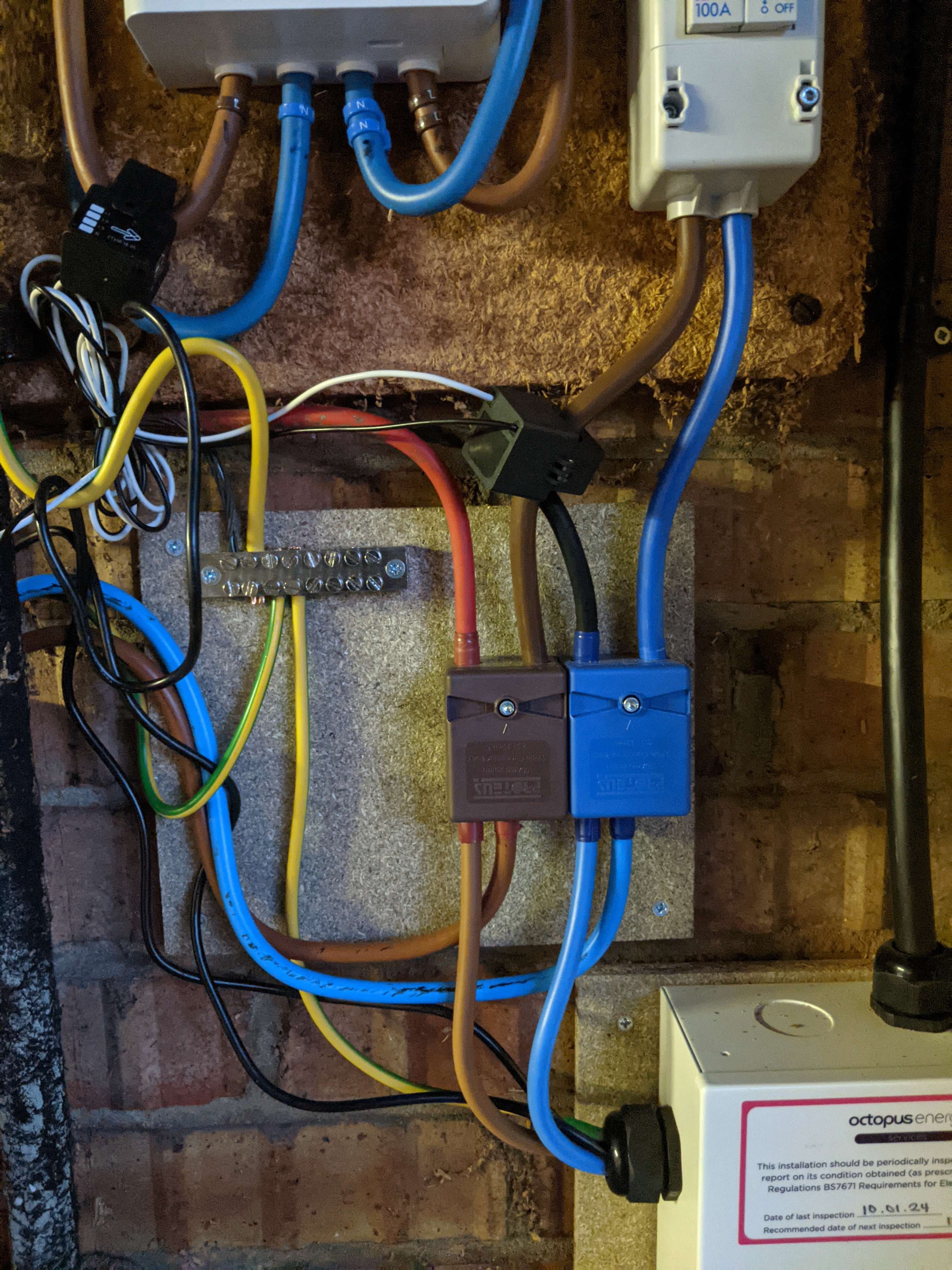

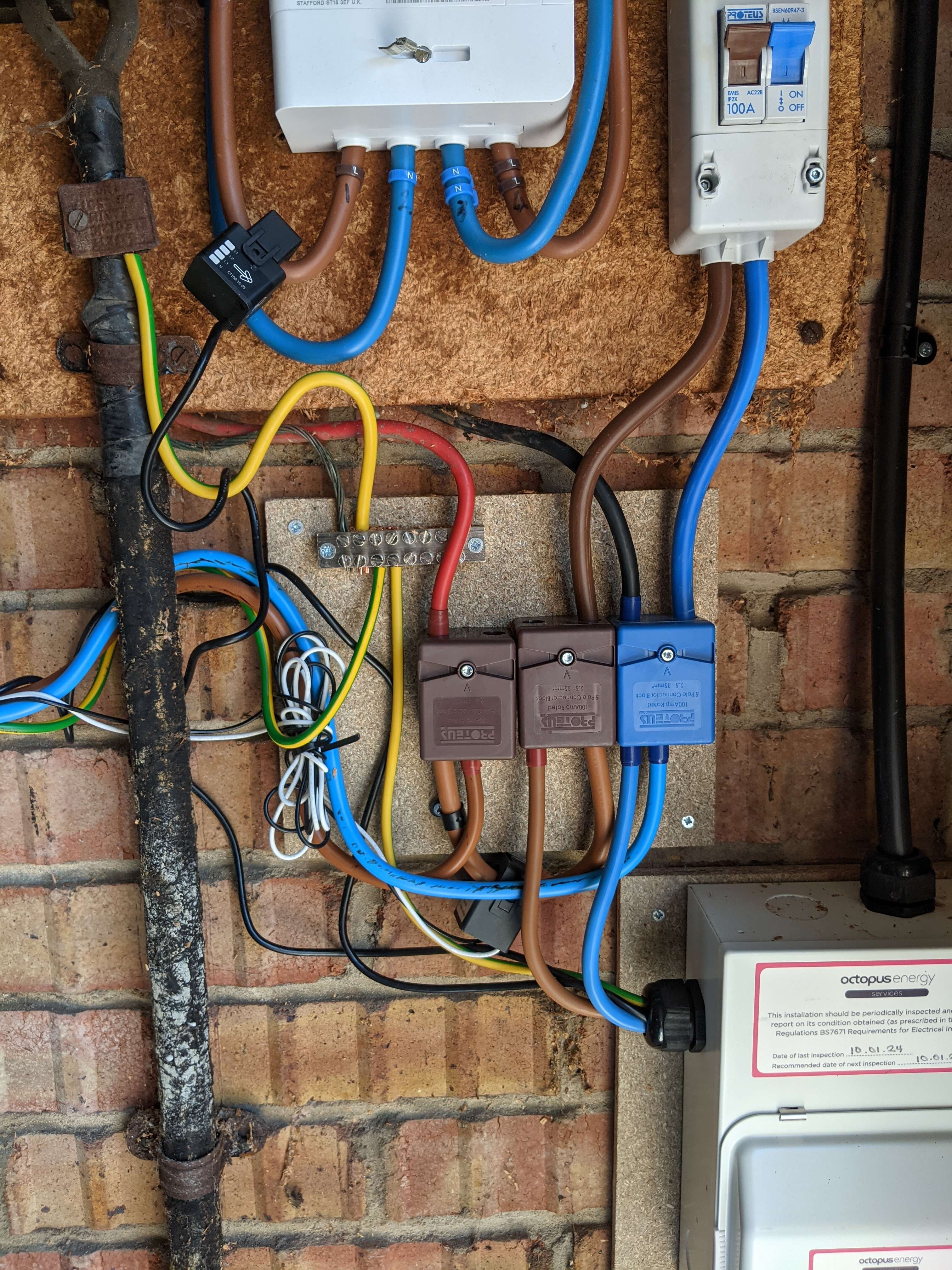
The GE is off to the lower left, and the house load (red/black tails) is off to the top-left. Smartmeter is at the top, with isolator to the right of it. Mini CU for the Zappi is on the bottom-right. The CT on the cable going into the meter is for the Zappi. The one after the isolator switch is for the GE. Even though they were on physically different cables, in the before picture, all the load went through both cables, and so both reported all activity. In particular, the GE was aware of the load the Zappi was drawing overnight, and wanted to discharge to cover it.

By adding a second splitted block, the GE clamp is now on the loop between between the two blocks. So GE now does not see any load from the Zappi.

With a similar sort of arrangement, one hybrid inverter would see everything to/from the grid, whereas the second would see only downstream of the first. Both see the house load.

To give a concrete example, consider cross-charging. In the case that both are measuring the actual grid connection, one starts charging and the other discharges to cover it. One that's charging sees that there is no grid activity, and believes it's doing the correct thing in consuming unused export. The one that's discharging sees that what it's generating is not going to the grid, and so believes it is covering house load, and is happy. This is a stable state.

For the explicit separation case: lets call the "primary" inverter the one that's measuring the real grid connection, and the "secondary" one the downstream one. Suppose secondary started cross-charging from the first. The primary believes it is covering house load, and so is happy to continue. But the secondary perceives that it is drawing from "grid", and so stops.

Or if you were to force-discharge from the primary, the secondary wouldn't see it, and so has no reason to consume it, and it would go to the grid as (presuambly) intended. You do of course have the problem that if the secondary force-discharges, the primary will consume it unless told not to.

If the secondary is spills excess solar that wouldn't fit in its battery, the primary will consume it. But unfortunately, it wouldn't work the other way round, since the secondary would not see power spilled by the primary. Would probably need some sort of invervention to manage that case.


D
#10 DD

geoffreycoan But the cross charging I see is always from inverter 1 discharging and inverter 2 charging, it’s never the other way round. The two CT clamps are one after each other on the meter tails. Which one is first I don’t know, could swap them round and see if the pattern of cross charging swaps round.

That's possibly just tiny differences in the calibration ? The cross-charging is presumably triggered by a transient in house load - eg kettle turning on/off. Each perceives the change slightly differently, and then how they react results in a stable (but undesirable) state.

P
#11 Pete UK

AndrewH

Hi,

This is the set-up I have with 2x Gen3 5.0 hybrid inverters. And 4x 9.5kW batteries. (2 on each inverter).

The Gen 3’s (which is what you’re asking about, not Gen 1’s or 2’s) do cross charge a lot and need to be managed somehow. If not they cross charge each other all day at up to the Max of 3.7kW. One discharging into the other continually (Usually it goes up to the max very quickly, but might flip flop 3 or 4 times a day when one gets empty!).

This set up IS SUPPORTED. It’s just not “recommended”.

To manage it you need either;

1) Home assistant
2) get on the GE “balancer” beta Trial
3) install the CEMS (which isn’t available yet!)
4) some other 3rd party control)

The earlier inverters behave differently as do the AC versions.

I’ve had a lot of problems with the batteries, support have been ok at fixing/ replacing things but just not very quick. I’ve still got some problems even after a year with the batteries (charging/ discharging rates at the moment) which are being looked at. When it works it’s great but it’s never been 100% working properly. (Maybe I’ve been unlucky?).

P
#12 Pete UK

DD

Yep that’s exactly it. When the house load increases a bit (which it does all the time) the one discharging increases its discharge. And then the other one increases its charge. Until one is discharging at max and the other charging at max available. It’s a positive feedback loop. Until one is empty then they flip.

D
#13 DD

Pete UK the Myenergi suite (Zappi, Eddi, etc) have a mechanism where each device can be set to have an export margin - effectively they're told to leave behind some of the excess. In this way, priority can be established. eg if Eddi is told to leave 200W, and Zappi 100W, then in practise the Eddi will stop, since the Zappi will always be willing to soak up some of the margin the Eddi is leaving.

I wonder if something similar could be done by deliberately miscalibrating one of the CT clamps ?

Playing with the CT clamps as above might at least eliminate cross-charging in one direction ? Would need to ensure the inverters' clocks are kept closely synchronised, so that they start and stop any forced charge/discharge in the correct manner. (Presumably simulataneously if they are peers, or perhaps slightly offset if they are primary/secondary.)

G
#14 geoffreycoan

Pete UK Its interesting to read the different behaviours of the different inverters, especially that your gen 3’s will ramp up to full rate cross charging. My Gen 1’s on the original firmware never cross charged which was an advantage of the old firmware as @hoggy notes, but since being on the ‘fast switch’ Gen 1 beta firmware (191/193) I do see cross charging but not at an awful rate.
It sounds like you get cross charging at any time of the day as well; I’ve only ever seen mine cross charge at night when they are discharging to meet house load. Maybe it’s because the Gen 1’s are slower to respond than the Gen 2’s and 3’s?

Anyway, I agree with the recommendation to either go to the newly approved multi-AIO setup or use another manufacturer.

So far I don’t think anyone on this forum has a multi-AIO setup, so real life feedback (as opposed to product testing) shared here yet

P
#15 Pete UK

What it really needs is for the demand value to be collected from one CT clamp, halved and then that demand sent to each inverters’ battery/batteries.

That way they’d all contribute half the damand. Charging and discharging in sync. (Ignoring some variability, and SOC errors from each individual battery obviously - but surely that could be managed with a small bit of logic also).

If you had 4 batteries, it’d ask each battery for a 25% contribution. If you had 6 batteries on two inverters, it’d ask for 1/6 from each etc.

If you had different size batteries it’d ask for the appropriate percentage from each.

If you have an EV charger, it would sense when that’s on with another CT clamp and you’d have an option to “do not discharge batteries when EV is charging” or “only discharge to house house load when EV is charging” or “whatever” toggle switch depending on your preference.

I’m anticipating this is what the CEMS will do; split the demand equally amongst batteries to keep them equal. But very little info on what it actually will do or how.

How does Pylontech or other multi battery/ inverter set ups work? Surely the demand is seen and just divided up equally amongst packs? Or do they have similar issues?

I’m sure it can’t be that hard can it? Or maybe I’m missing something and it’s a lot more complicated.

P
#16 Pete UK

geoffreycoan

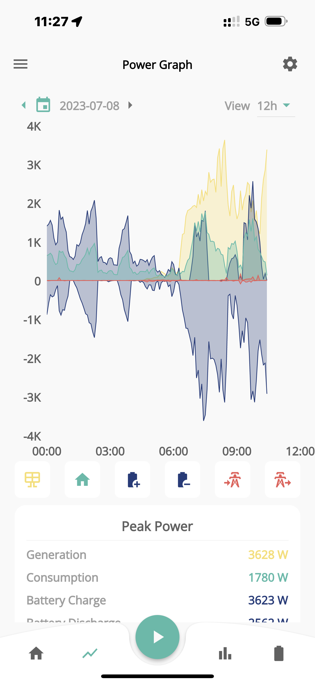
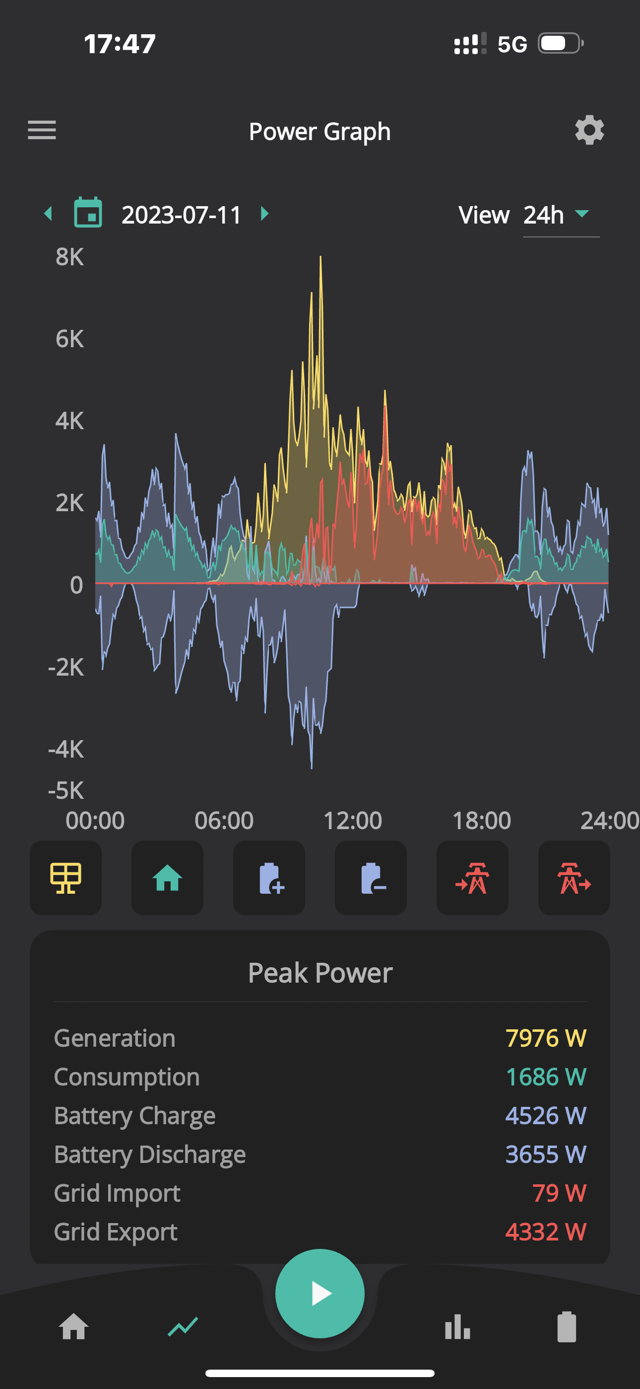
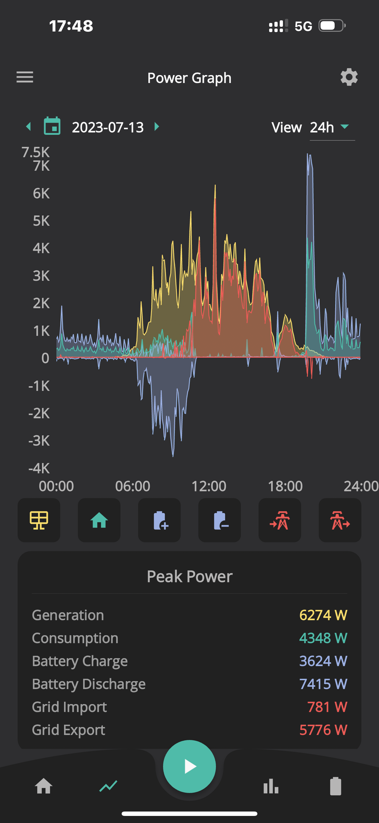
Yes it is interesting. This was a chart a week after my install a year ago. (I can only find this one screenshot quickly). If you paused the batteries and re-started them, they reset but then ramped up the cross charging again. This was pre getting on the balancer software. Which helped reduce it a lot. The balancer basically pauses and plays the batteries via the API to keep “resetting” the mis-informed demand. I get tonnes of API commands sent a day !

  • not that I mind, as it effectively fixes the problem.


D
#17 DD

Pete UK I’m anticipating this is what the CEMS will do; split the demand equally amongst batteries to keep them equal. But very little info on what it actually will do or how.

I’m sure it can’t be that hard can it? Or maybe I’m missing something and it’s a lot more complicated.

The inverter has quite fine control over battery charge/discharge rate, but the modbus interface provides a relatively crude level of control (approx 100W resolution on my system), and quite a lot slower. (I was using it to try to micro-manage charging rate, to try to maximise export without clipping. But I've now find a much better scheme.)

I don't know if CEMS will use the modbus interface, or has some faster access. Or perhaps it can enable a modbus mode where the inverter pushes out status updates, rather than waiting to be asked.

Could possibly leave one inverter in eco mode, allowing it to respond to small fluctuations, and have the others with fixed charge/discharge rates, adjusting them on a longer timescale to contribute roughly their fair share.

P
#18 Pete UK

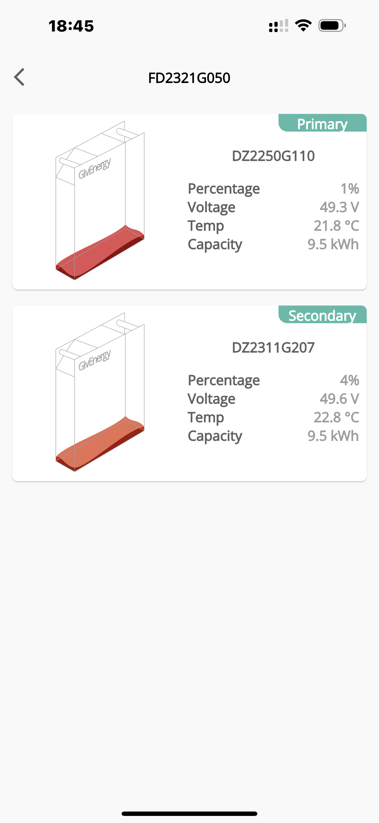
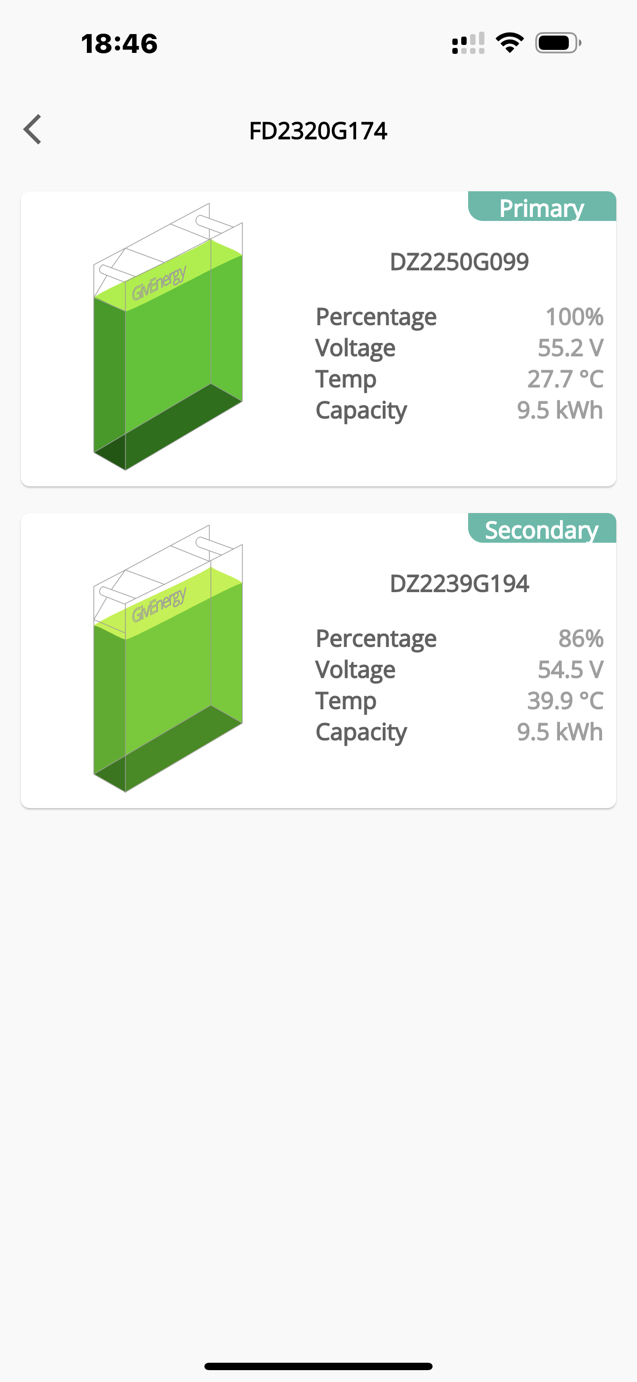
Before and after being on the Balancer software;

Quite a difference….


P
#19 Pete UK

DD

Would this suggestion not work and also be better?

Pete UK What it really needs is for the demand value to be collected from one CT clamp, halved and then that demand sent to each inverters’ battery/batteries.

D
#20 DD

Pete UK But if one battery runs out, you want to ensure the others will take up the slack. Or say 1 battery of 4 fills up, you want the others to take 1/3, not 1/4, of excess export.

P
#21 Pete UK

DD

Yep. Surely that could be built in to the logic. ie if one is empty - divide by 3 instead of 4 and send that to the remaining 3

Although they should all empty reasonably equally though, no?

#22 hoggy

DD it's in the library so that means it modbus accessible (modbusable? anyway..) https://github.com/britkat1980/givenergy-modbus-async/blob/getting-ready-for-1.0/givenergy_modbus/model/ems.py
Looks like it can split things out up to 4 ways /inverters currently.
I'm lead to believe that bad things happen if you try and talk to the inverter directly and bypass the CEMS box as it's probably constantly sending data back & forth as if the CPU were to reside internally.


Might be Gen specific compatibility, as only Gen 3 and AC3 have this little line.
A308/D308 notes:

  1. Add EMS CPU parallel control parameters

so presumably this mode lobotomises the inverter and it just does whatever it's told from external source, be that USB or RS485.

Gen 1 & 2 might be out of luck...

D
#23 DD

Pete UK Yep. Surely that could be built in to the logic. ie if one is empty - divide by 3 instead of 4 and send that to the remaining 3

Yes. But it means it's no longer just a dumb divide-grid-reading-by-N (which can be done in hardware), and needs a more active participation.

Pete UK Although they should all empty reasonably equally though, no?

Perhaps depends on how much solar they see ? Perhaps there's one inverter for each of N,E,S,W-facing panels.

G
#24 geoffreycoan

hoggy Gen 1 & 2 might be out of luck...

What a surprise

TBH I am happy enough with my multi-inverter setup. I plan to make some changes to the way that Predbat balances the inverters (which doesn't work correctly at the moment) and the remaining small cross charge niggle will go away for me. I also fear CEMS may well disrupt GivTCP and all that depend on it, plus being cynical I expect it to be a complex thing that'll take a while to get right in the field so I'm not banging on the door of wanting one.

I do feel sorry for the people with multiple AC3's who have cross charging problems with their plant setup as it seems they've been left on the shelf.

A
#25 AndrewH

Wanted to say thank you for all of your replies and interesting thoughts. As an installer we have decided that our client isn't going to want to manage this set up and would prefer to have the full support of GivEnergy and warranty. We have spoken with Technical Support at GivEnergy and they have advised us not to go down this route. A product is in the design stage to allow parallel connection and we will wait for that to come to market. We have decided to use another product on this occasion.