So I've got my head around how to stop my Giv Battery being drained by my EV charger. It all makes sense to me now.
But I've hit a couple of snags.
I used an electrician to replace my single CT clamp (which links to my Giv inverter) and he was in contact with Giv support. I asked for the CT clamp to be placed between the Henley Blocks and the house consumer unit, after the EV charger load had been split off.
Problem 1 was that the Giv support advisor was adamant that the CT clamp be placed between the meter and the Henley block, before the EV load split. I explained that this would drain the battery when charging my car, but to no avail.
Problem 2 was that the Electrician and I moved the CT clamp anyway. Sadly it made the problem worse! The Giv app detected a massive draw from the home which it tried to meet. We tried reversing the direction of the CT clamp and repositioning it but nothing worked. So we agreed to do as the Giv advisor said.
If anyone has any idea why this hasn't worked I would be very grateful
EV Battery drain - Technical confusion
What EV charger do you have as many use an additional CT clamp on the solar line to monitor the solar current. Our zappi can be set to ignore any solar export and or battery on the solar system.
Speedy I think the simplest way to view things is that, in eco mode, the inverter strives to keep the CT clp reading 0. If it detects import, it increases battery discharge; if it detects export, it decreases battery discharge (or increases charge).
Bear in mind also that it doesn't measure house consumption: it infers it based on grid import/export and how much it is generating/consuming. The CT clamp needs to see the power to/from the inverter itself along with the house load.
A photo might be helpful.
Can you remind us what kit you have - hybrid inverter?
You mighr be able to use WonderWatt which has some features to manage battery discharge while EV is charging.
They have a free trial period to see if can work for you. I use it to limit the battery discharge to 'house load' overnight when the EV is charging.
Ortwin
Hi Ortwin,
Thanks for getting involved.
My EV charger is a nine year old Polar model. It has zero intelligence. There is no User Interface or app. Probably for that reason it does not have its own CT clamp.
I've held off replacing it in the hope of eventually moving to a V2X charger.
DD
Thanks for the explanation DD. I hadn't realised the CT clamps limitations or even how ECO mode really works. It might explain how the readings were moving around erratically, but the new position was still what I need.
I have taken photos but cannot get them to upload to this message. I get "Oops! Something went wrong. Please reload the page and try again.'
Is there a trick to it?
alan_johnston
Thanks Alan,
I will look into Wonderwatt and see how it works.
Many Thanks
Alan
Speedy I have taken photos but cannot get them to upload to this message. I get "Oops! Something went wrong. Please reload the page and try again.'
Is there a trick to it?
If you can’t upload its probably because the photos are too large. I use photoshrinker https://apps.apple.com/app/id928350374 to reduce the image resolution and then they upload fine.
The wonderwatt option is good if you are on Octopus Intelligent Go and Octopus is scheduling the charges (i.e. not Ohme), to program the inverter to start/stop charging aligned to the OIG slots.
Thanks Geoffrey
I’ll get right on it
Alan
geoffreycoan
Photos


Did that work? I only see text?
yes the photo loaded ok
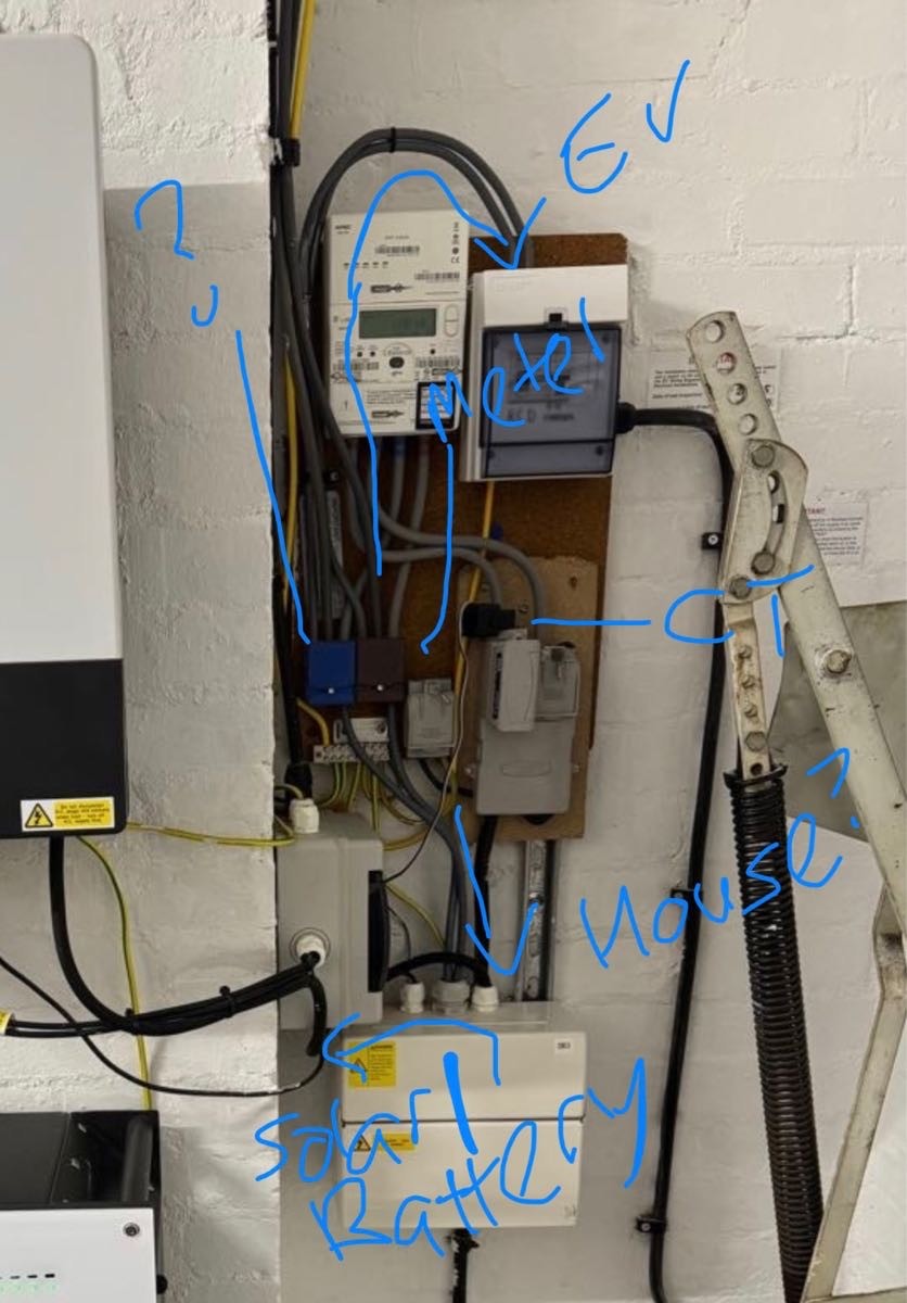
looking at the wiring and annotating what I see

there’s a cable off to the top from the Henley block that isn’t clear what it is.
But if the CT clamp were moved from the incoming grid feed onto the cable that goes down into the consumer unit and your battery/solar then that would mean the solar/battery wouldn’t see your EV charging at all. However it would also omit whatever load is connected to the cable going vertically upwards
You could move the CT clamp yourself, you simply unclip it and clip it around the cable from the brown live Henley block into the consumer unit
If you needed to include the consumption from the vertical cable then you’d need to get a couple of extra Henley blocks installed to move around the connections, but its only an hour or so’s work
Thanks Geoffrey
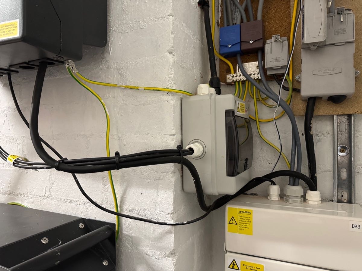
In response to your question there are three leads on the top of the brown Henley Block. One is the live feed from the meter. One is the lead to supply the EV charger. The third supplies the Home and leads to the consumer unit, out of shot, higher on the wall.
The last lead enters the bottom of the Henley block originally from the hybrid inverter. I guess this must supply solar and battery power to the system and be directed to the house as required.
I’ve checked your wiring diagram and you’ve got the easily observable bits spot on.
So my plan is to relocate the CT Clamp on to the lead that exits the top of the brown Henley block and heads up to the home consumer unit. Making sure I get the arrow pointing towards the CU.
I guess I should ignore the readings for a while until it settles down. Not difficult as the inverter has lost WiFi.
Do you agree? Is there anything else to do?
Many thanks for the help and guidance
Alan
Speedy The last lead enters the bottom of the Henley block originally from the hybrid inverter.
What is "originally" here? Do you mean it used to do that but had changed? Or that it originates from the inverter?
If the latter, then I think there's still a problem. If I understand correctly, one lead in from meter, one out to ev charger, one to inverter and one to home. So there is no tail carrying the combined current of home plus inverter, which is what the system expects.
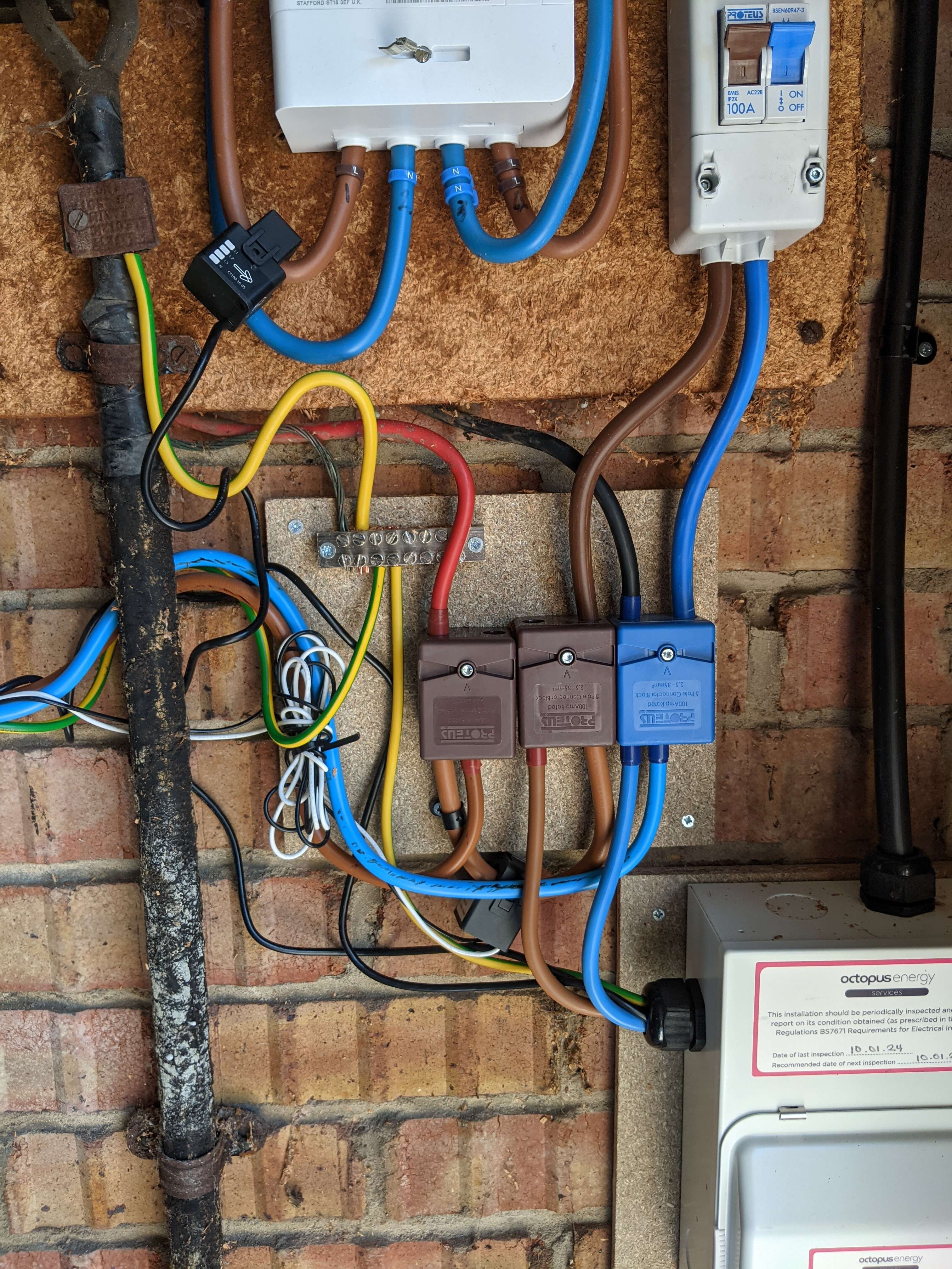
DD my system looks like:

where first brown block splits off just ev, and then the cable linking the two brown blocks carries combined power of home and inverter (plus heat pump added after picture was taken). The second brown blocks splits those off to their separate destinations.
The blue block is like yours, and splits three ways.
DD If I understand correctly, one lead in from meter, one out to ev charger, one to inverter and one to home. So there is no tail carrying the combined current of home plus inverter, which is what the system expects.
I think you have it spot on, as you said the inverter will try to balance the energy flow through the CT clamp to zero by either charging or discharging the battery.
There isn't a position to put the CT clamp to do this because everything currently goes into a single Henley block.
What is needed is to introduce a new pair of Henley blocks, taking the cable that currently goes into the meter into that block, then coming out of the HB will be two connections, one to the EV charger and one to the existing HB
Like this:
----- Grid ------------ HB new -------- EV charger
|
CT clamp for inverter
|
Existing HB ------ House
|
Inverter

Could try 2 CTs in series (the EM115 isnt actually measuring current in the traditional way). This is not my work but has been tried successfully:
I have a "Split core current transformer 100A/0.333v (33mV)" here that I'm planning to connect in parallel with the one connected to my EM115 and to then clamp "backwards" on the tails to my EV CU to subtract the power going to it. Is it just a case of cutting CT wires and connecting with Wago or similar? Do I need to power down CU the EM115 is in and/or disconnect the clamp? I'm fairly sure the answers are "Yes" and "No" but would very much like to not mess this up.
And
Summary: It works. But 1) definitely power off inverter CU and work directly at the EM115 as it's screened cable so a hassle (ask me how I know!) if you cut it, 2) The CTs need connecting in series and not in parallel. In parallel I just saw 0W. So disconnect (say) a black at the EM115, connect the white from the 2nd CT to the EM115, and then join the black+white together with Wago or a bit of terminal strip.
hoggy and if you say that quick enough @hoggy then everyone will think its a dead straight forward thing to do 🤣
It’s a neat solution, in effect making a ‘net CT’ clamp from two CT clamps wired in series, one backwards to subtract the EV power.
For anyone who wants to try this and doesn’t have a spare CT clamp, Shelly have a black friday sale on at the moment. I’ve just bought a fourth Shelly EM with two CT clamps as they were 60% off the original price. A single CT clamp wouldn’t be much. Or you can doubtless buy them from ebay or Amazon or aliexpress if you can wait
geoffreycoan
Hi Geoffrey,
It seems as though I need rewiring for the CT clamp fix to work.
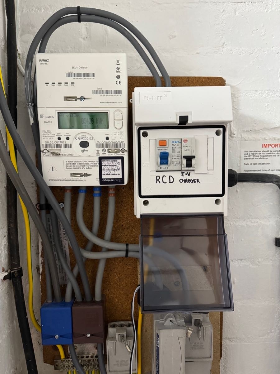
In the hope that the board might confirm that diagnosis here are some better photos.

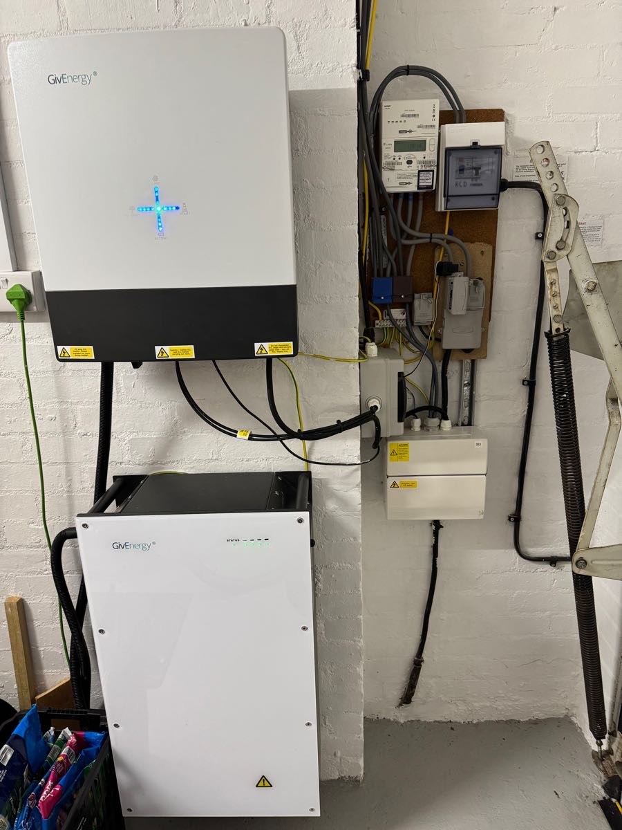
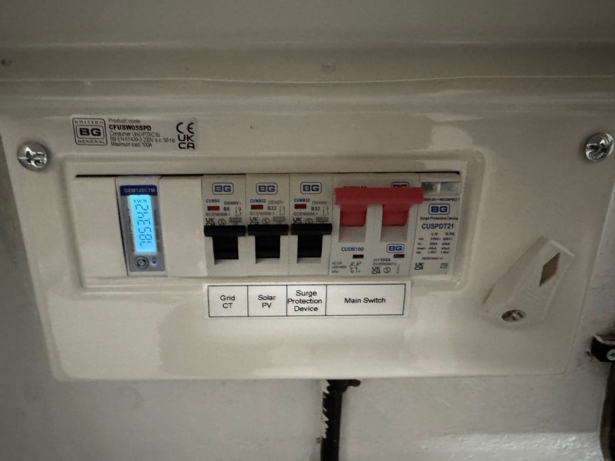
This one shows the wiring between the Inverter and the White metal box marked DB3 and PV system - Main AC isolator. The inside of the isolator looks like this.

So, it seems entirely probable that there is one feed from the meter into the Brown Henley Block and three out. These go to the EV charger, the Home and the Inverter. (By the way the photo is a bit misleading. The mains supply rises up behind the PV Isolater. It does not fit into the same orifice as the thick black cable from the inverter. And I do not imagine that the mains links directly to the PV Isolator before it goes to the meter!)
I don't know if that is enough info to reach a conclusion whether I can simply replace the clamp or I need to rewire, or buy another clamp and position them precisely.
But it's looking as though it's not going to be a simple fix.
Regardless of the result, I am so grateful for the expertise this board has shared with me.
Thank you!
Speedy I think we are concluded that with the current 1 in 3 out in your single Henley block there isn’t a way to reposition the CT clamp to measure inverter and house energy together separated from the EV load.
And this explains why when you moved the CT clamp to the house cable it didn’t work. The inverter started discharging the battery but where the CT clamp was positioned it didn’t see the effect of that discharge so it kept on ramping up the discharge.
If the inverter and house cables were side by side you might have been able to get the CT clamp around both the house and inverter cables and that might work, but I suspect you’ll find that the CT clamp won’t clip around both cables, they’re too thick.
Adding a second CT clamp to the wiring, @hoggy says it works, personally its not something I would advocate as you are disturbing the CT clamp wiring and if anything goes wrong then GivEnergy might blame that for the problem. If your installer did that then different matter.
The simplest thing is to add a new Henley block and reroute the cables as discussed. You only actually need a single Henley block on the live as the CT clamp only goes around one cable, the neutral can be left as-is.
I am NOT advising that you can add the Henley block yourself and change the cables around after first turning off the master grid feed, and I am NOT suggesting that is the sort of thing I have ever done. Its a straight-forward electrician task, probably cost them more in time to do the paperwork for the invoice