hello
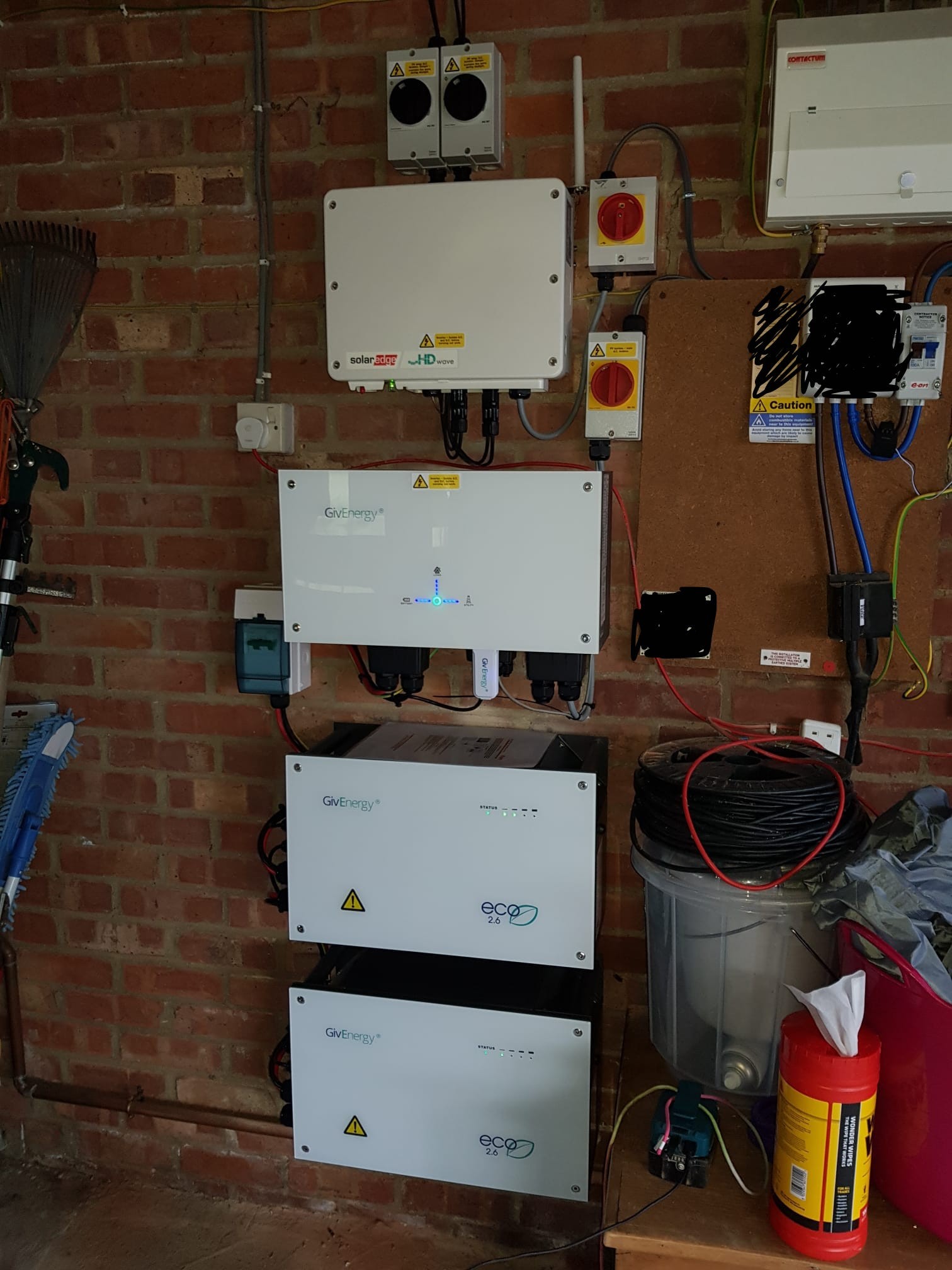
my solar edge inverter has a green flashing light.
my givenery inverter (the thing with the arrows and green light in middle) is solid.
I can send a command from the app/portal to charge my battery from the grid and the works.
My system says solar and grid are neutral.
I cannot monitor the grid import feed.
My inverter tables of data say it is in waiting mode (but goes to normal when I sent grid to battery).
I have updated firmware
restarted system remotely and hard restart on the wall
I have synced time
I have reset to defaults vis setting
Anyone have any tips?
I have been waiting 3 weeks for givenergy to get back to me but no luck which is very disappointing.
I have not touched settings under the remote control but it's eco mode enabled...
ac charge upper limit is toggled on,
enable dc discharge is toggled off
ac charge enable is toggled off
Happy to provide more info (if I know where to look!)
thanks for any help
S
#2SteveCook
Is you EM115 glowing green. It should be near the incoming electricity supply, possibly in the consumer unit and needs to be powered
Y
#3yb1
SteveCook yep - EM115 is glowing green, and GEM120CTM next to it is blue.
have just checked green light on solar edge and givenery inverter are both in waiting model (flashing green)..
this really has all occurred since I had an ev charger installed - but that is now turned off.
They did not seem to put ct clamps in the correct place....
what I dont know is would I ahve had ct clamps before - and have they moved them..could that make such a difference?
thanks for any info but I prob am not explaining everything too well!
S
#4SteveCook
The meters need CT clamps around the mains cables so the inverter knows what is going on. They have to be fitted the right way round(there are arrows on the clamps. Maybe your installer messed with them when the charger was installed. Can you get the installer back
Y
#5yb1
SteveCook they are coming back on 7th January.
I am so annoyed - they are very well known installer and I was so careful to explain to them that it had to work with battery and solar....
I wish I had taken a photo of the installation before they arrived - then I would know what has moved.
super annoyed!
Y
#6yb1
I actually do have a photo - and I can see the ctclamp location before and it definitely not in the same place anymore.
I can post before and after photo if it would help??
but understand if not
D
#7DD
yb1 yes, before and after photos would be helpful. Might need to compress (reduce quality) to be able to post them here.
Y
#8yb1
this is photo before (so original installation)
Y
#9yb1
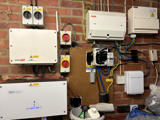
unfortunately I dont seem to be able to upload the after photo :-(
Y
#10yb1
but I now have one clamp on a wire from the top of lower red isolator switch
and one on brown wire coming out of the top of small grey box next to the meter. (before it was on brown wire on bottom)
G
#11geoffreycoan
yb1 the grey box next to the meter is your main isolator switch for your house. It shouldn’t matter which side of the switch the CT clamp is installed on.
Is that the GivEnergy CT clamp, the one shown on the original photo that is black with a white wire on it?
The red isolator box is to turn your inverter feed to the house off. The CT clamp in front of that may well be going to the EV charger to detect solar power?
One possibility is that the CT clamp by the main isolator switch has been installed the wrong way round, you can simply unclip it and rotate it 180 degrees and clip it back onto the brown cable, No electrical risk to you at all.
From where I think your CT clamps have been installed it very much looks like your installer has not wired it up in a way that will prevent your battery discharging when your EV starts charging. Its been described several times on this forum before, and see this blog post https://www.philiprsteele.co.uk/post/cars-solar-panels-batteries-ct-clamps-and-henley-blocks describing how the EV charger should be installed
Y
#12yb1
geoffreycoan
thanks for the information. I hope it's okay to ask a few questions before I turn the ct clamp.
I wish I could load the after photo but it wont let me know - so hope my description of where they are now is clear.
so yes the CT clamp by the main isolator switch is the original one from givenergy. I will turn it around as I know how to do that.
for the new ct clamp that is above the red isolator box - yes I believe this is related to the new ev charger. am I right that if my ev charger has been turned off fully then that ct clamp is not doing anything. so I can ignore it (and wait for the ev charger installer to come back).
I will keep the post on the henley blocks. I can see two of these on my system ...and I will be so annoyed if they have got it wrong because I couldnt have made it clearer about not discharging the batteries.
I got a zappiglo - I hope I dont regret it.
thanks
Yvonne
D
#13DD
yb1 I wish I could load the after photo but it wont let me
Try lowering the resolution / compressing it - might just be too big.
I assume that's similar to earlier zappi I have. It can have multiple CT clamps: one to measure total import, so it can reduce charging power to protect main fuse; another to measure solar, so that it can report solar - not sure which it uses as a basis for charging from excess solar. (I repurposed second one to measure heat pump consumption.) So correct placement depends on what it has been configured to measure
Y
#15yb1
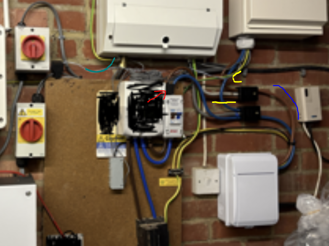
finally managed it- this is what the system looks now. hope its clear enough
G
#16geoffreycoan
yb1 so yes the CT clamp by the main isolator switch is the original one from givenergy. I will turn it around as I know how to do that.
let us know if that works
for the new ct clamp that is above the red isolator box - yes I believe this is related to the new ev charger. am I right that if my ev charger has been turned off fully then that ct clamp is not doing anything. so I can ignore it (and wait for the ev charger installer to come back).
yes you can ignore that, its only for the EV charger, and is likely to monitor solar generation as said
I will keep the post on the henley blocks. I can see two of these on my system ...and I will be so annoyed if they have got it wrong because I couldnt have made it clearer about not discharging the batteries.
Looking at your photo, and zooming it in, yes I think they have got it wrong
the red arrow is your givenergy CT clamp which is on your main grid feed after the meter and after the master switch (it was originally before the master switch, but that change makes no difference)
I am guessing that from the two henley blocks the blue cables feed to your EV charger and the two yellow cables feed to the consumer unit directly above the meter (which in turn feeds the inverter via the teal wire) and the house consumer unit top right?
With the arrangement of henley blocks the inverter will "see" all current passing from grid to the EV charger. You don't want this.
New henley blocks need to be fitted with a cable from the existing EV henley block to the new block and the two yellow cables going to the two consumer units. The GivEnergy CT clamp can then go on the cable between the EV Henley and this new Henley so the GivEnergy CT never sees the EV charge load.
Y
#17yb1
geoffreycoan
thanks - I will print this off to ask the installer about it.
Could I ask - because they are not going to be coming for a few weeks - and I have turned off the ev charger (at the white box on right)....is there anything I can do with CTClamp so my system can work as before?
Or it will only work again once they have come back so nothing I can do in the meantime.
thanks again
P
#18pwdst
Moving your CT clamp and/or turning it the right way around are unrelated to any wiring changes your installer might need to make to stop your batteries being discharged into your car. If it is correctly located and oriented then the GivEnergy system may become usable again.
It is also possible to use automation to ensure your batteries are charging or paused at the same time as your car is charging so it's not the absolute end of the world if the wiring changes cannot be made.
G
#19geoffreycoan
yb1 as pwdst says, these wiring changes are to stop your battery discharging into the EV. When the EV is not being charged everything should work as normal without any changes being made.
The fact that it isn’t suggests either the CT clamp is round the wrong way, or the cable is damaged or the EM115 is turned off (little like circuit breaker box with green numbers should be lit up).
D
#20DD
geoffreycoan if the CT clamp was the wrong way round, I'd expect system to be unstable, reacting incorrectly to changes. Eg if you turn on a light, there's a small increase in grid import, so battery should (in eco mode) increase discharge to counter it. But if clamp is backwards, system will see a decrease in import, and reduce discharge. This increases import, and battery further reduces discharge, and this positive feedback drives battery to max charging. Similarly, if Sun comes out, export will cause battery to max discharge rate, the opposite of what's wanted
Y
#21yb1
Restored ctclamp to original position and a full restart and repair of the solar edge has resolved the issue :-)
Have full feed and monitoring - fantastic!
EV charger installers coming back and I willl get the system checked again and make sure directions are all working.