Stuck on 200w discharge

13 comments started 2026-02-26 last 2026-03-05
GivEnergy ProductsHybrid
L
#1 Lmcde3

Hi all. I hope you can help.

A few days ago I had some electrical work done on the house. This did not involve the giv energy hybrid system that has been working well since install. However, the system was turned off/isolated and hasn't worked well since.

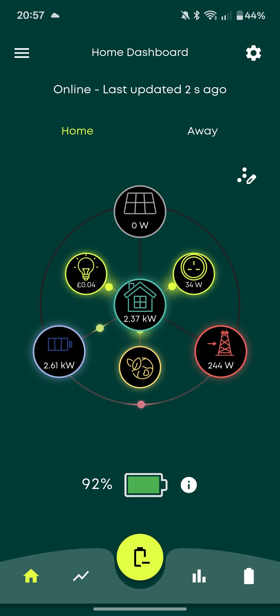
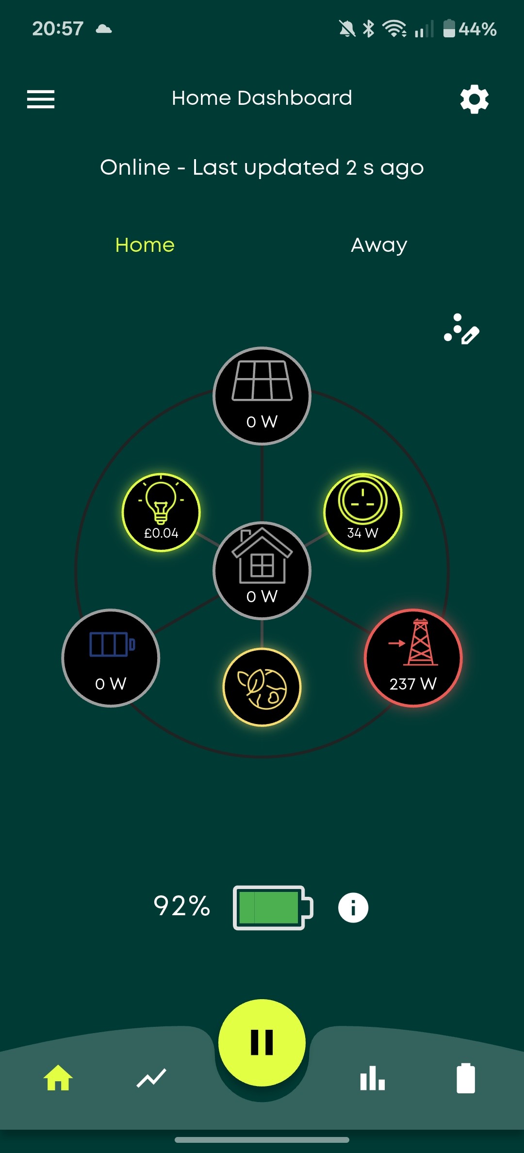
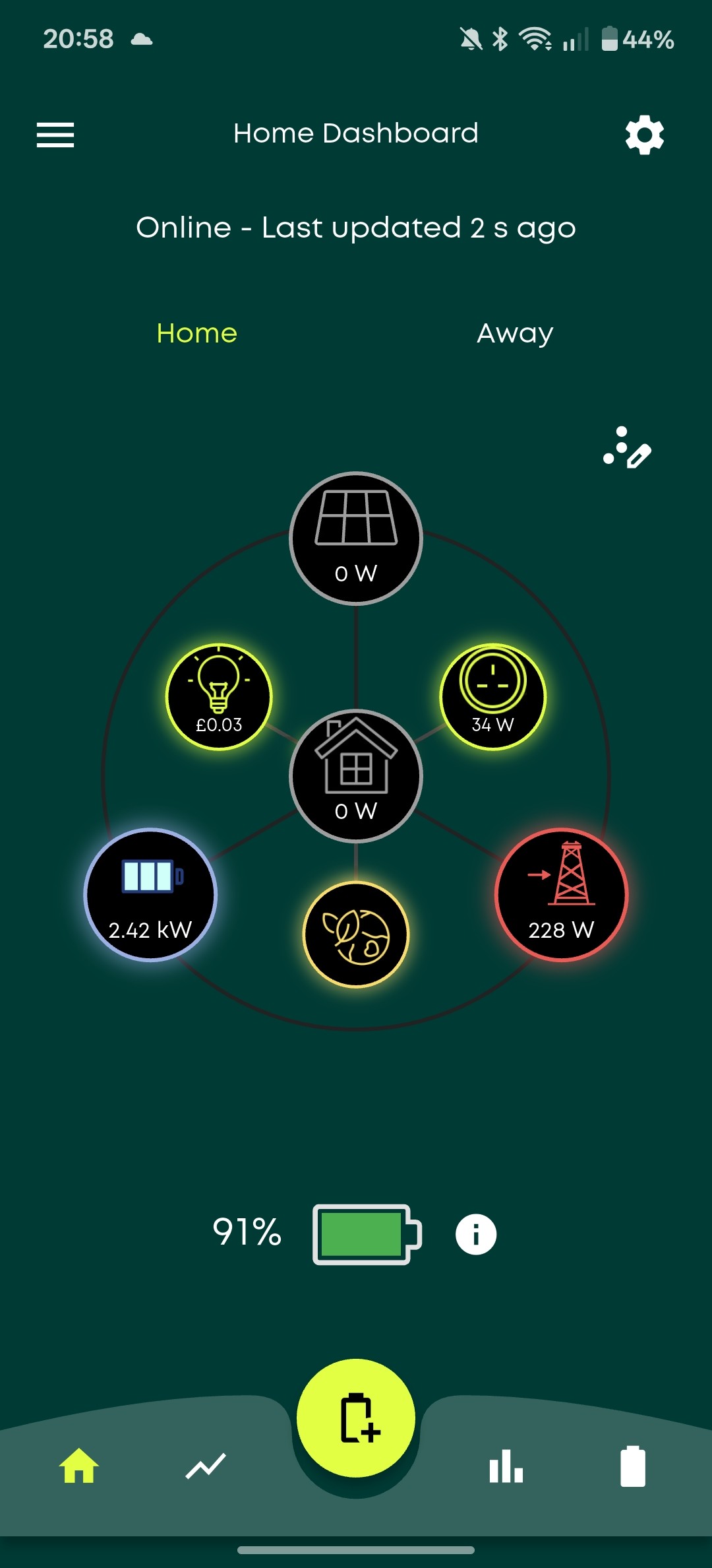
When looking at the readings via the local app connection I see the following (picture attached).

In normal mode I see 200w discharge to the grid but no discharge from the battery and no solar generation (it's now dark). The house load is 0.

When I force discharge the battery, I see 200w export to the grid and full discharge from the battery to the house.

When I force charge the battery, I see 200w export to the grid, the battery fully charging, but I don't see any load to charge the battery coming from anywhere and the house load is 0.

I've checked the CT clamp and it is facing the right direction.

Thanks for any help you can give.


P
#2 pwdst

Is the EM115 meter powered? It's also interesting that the force discharge shows high household load, could the CT clamp have been relocated?

L
#3 Lmcde3

pwdst Hi. The 115 is lit yes. Yes, the CT was moved from inside the consumer unit to outside of it yes. I've checked and it is on the incoming supply pointing towards the load.

G
#4 geoffreycoan

Lmcde3 the instructions for which way round the CT clamp goes are inconsistent in the givenergy document, and I have heard that some CT clamps are actually manufactured with the arrow in the opposite direction.

Try turning the clamp around.

Check on the givenergy portal whether there are any notifications from the inverter, failure to talk to the EM115 for example might indicate the cables have come loose at the inverter.

If this doesn’t fix it, I’d get the electrician back to sort out the problem.

D
#5 DD

geoffreycoan I think having CT clamp wrong way round would behave differently - rather than trying to keep grid activity to a minimum (with negative feedback), it would amplify perturbations and end up on max export.

G
#6 geoffreycoan

DD I agree when my CT clamp was on the wrong way round it would just export madly. The OP has had some work done, they mentioned moving the CT clamp, so trying to identify what has changed and what the cause could be

D
#7 DD

geoffreycoan yes, definitely points to CT clamp problem. But sounds like no reading, rather than inverted reading.
Could look at the reading on the em115 - that distinguishes whether problem is upstream or downstream of that.

L
#8 Lmcde3

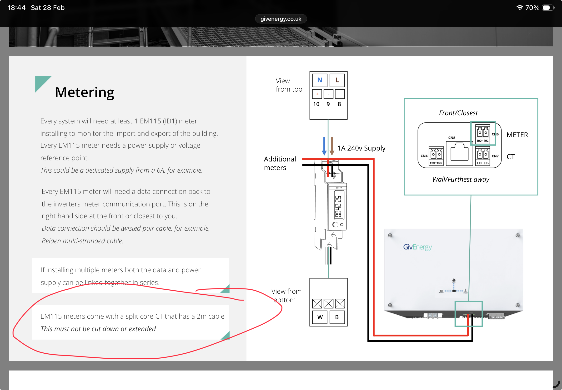
Thanks for the replies and thinking. I've taken a good look at the CT clamp and I can see that it's been extended which I think may be the issue.

The electrician is happy to come back so that's not the issue, its just deciding what's best. Id need 3m of wire for the clamp so is it best to move the OM115 or do you know of a suitable CT clamp with longer wires?

Any other ideas are also very welcome. Thanks.

T
#9 TX200

Lmcde3 yes, I seem to recall extending the wiring on a CT clamp can impact the reading. Have a Google and see what you think.
Might be possible to use a LoRA (acronym from memory, hopefully that's right) to transmit the readings over radio.

G
#10 geoffreycoan

Lmcde3 I've taken a good look at the CT clamp and I can see that it's been extended which I think may be the issue.

givenergy installers training guide:

https://givenergy.co.uk/wp-content/uploads/UK-End-User-Mangement-Installer-Training-Manual.pdf

On my own installation the meter cupboard is on the opposite side of the wall to the inverters and there’s a big loop of the CT clamp cable where the installers circled it up rather than cutting it short.

Think you need to get your installer involved

D
#11 DD

Lmcde3 extending the CT clamp would change inline resistance and so affect the calibration. But the connection from inverter to em115 is presumably digital and so length has less effect.

S
#12 SteveCook

My EM115 is the other side of the house (bungalow) to the inverter and connected by about 25m of Cat5 cable. The EM115 is in the consumer unit next to the incoming supply. It is probably easier to move the EM115 and put it a single gang plastic enclosure and extend the T&E and Cat5 cables, rather than playing with a proprietary clamp and cable

L
#13 Lmcde3

Hi all. Thanks again for your help here. I appreciate the replies.

In the end it was the CT Clamp. I bought a new OB115 CT Clamp and replaced. It's now working. I take the issue to be that the CT clamp is very sensitive and the wires cannot be shortened as directed in the manual.

Thanks very much again for your help.