CT Clamp Configuration

45 comments started 2022-11-03 last 2022-11-10
CommisioningGivEnergy ProductsHybrid
S
#1 sbird

I have just had a Solar Panel / Hybrid Inverter / Battery system installed. However, it has not been behaving correctly. Most of the time Load Power shows as 0W, even if I put the kettle on. The PV Power and Battery Power / Percentage graphs seem fine. However, Grid Import / Export / Load are not correct. Periodically the Load "appears" to jump from zero to a high value (e.g. 6KW) along with Grid Import (e.g. -2.9KW) and Battery Power (e.g. 2.6KW).
At first I thought there must be some "real" load on the system, so I isolated everything else in the house, but it still occurred periodically.
After reading other discussions on the forum my theory is that the CT Clamp has been fitted the wrong way around and so the Import / Export / Load figures are invalid / reversed.
Does this theory sound reasonable to others with more experience ?
Is there any GivEnergy Inverter configuration that I could apply to compensate for the reverse fitting of the CT Clamp ? - this would be a temporary solution to test the theory, ahead of the installers correcting the problem

Any feedback would be appreciated

T
#2 Tim

sbird Load Power shows as 0W, even if I put the kettle on.

Your inverter should be set to ECO mode with all the timed settings disabled. The CT clamp could be fitted the wrong way round, but that would simply show kettle load as export, so I suspect that the EM115 isn't working correctly. If the CT clamp is fitted the wrong way round, then unclipping it and putting it the other way round is fairly simple to do. They are usually fitted in an accessible location rather than within a consumer unit.

Maybe just give your installer a call. They will have engineer access to your plant and should be able to do some diagnostics without coming out to you.

#3 TheDragon (GivEnergy)

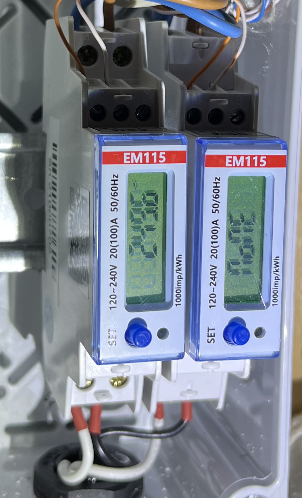
There is a CT (Current Transformer) clamp, on the EM115 (Small white meter with green display), likely in or near the Consumer unit.
This then links back to the Meter port on the hybrid inverter.

The clamp is a small black clip on block. You could if this is not in the consumer unit itself, see if it is in fact on the Meter Live tail (Thick brown wire from your DNO fuse to Meter). It has an arrow on it, which needs to point towards the Consumer unit (Load).

If this clip is not accessible, do not try and open your consumer unit. Call back your installer.

If the clip is correctly pointing inwards towards your CU, call the installer back, as there is an issue with the EM115 meter or its wiring.

Edit.
You may also have a notification in the portal, Meter Comms fail, or other error relating to this meter input

#4 dbt85

Just to be sure, how are you reading this data? In the online portal which only updates every 5 minutes or in the app which is connected on the same wifi network as the inverter and so reading local data every 10 seconds or so?

S
#5 sbird

Tim
Just to confirm:

  • The Inverter is in ECO mode and timed settings are disabled
  • There is an OB115, which I assume is equivalent to an EM115, but also a EML M21 meter (function unclear)
  • There are periodic peaks of apprent "export", which might relate to kettle / microwave
S
#6 sbird

dbt85
I am looking mainly at the data that is uploaded to the website. The app does not reliably connect to the local inverter (e.g. 1 in 10 attempts). There is a wifi dongle and a strong local signal (5m from the wifi router), but the dongle only appears on the network sometimes, as confirmed by periodic network scans

S
#7 sbird

TheDragon (GivEnergy)
Where on the portal should I look for Meter Comms failure?
Under Inverter / Notification the only event recorded is "Check Connection on Battery", which occurred durring the installation

#8 TheDragon (GivEnergy)

sbird

Ok, if there is no notification there, then at least it has comms with the meter. Just maybe receiving duff information.

A test.
Switch off all solar, pause the battery. Wait 5 mins and record grid import (Has to be import as no other source)
Switch the kettle on, does the import increase by 2kw? Or what ever power your kettle is??

#9 dbt85

sbird Part of your problem here could be that the website only gets new data every 5 minutes and it's just a snapshot. The totals it provides should at least be accurate though. If for some reason the dongle isn't remaining connected then it might not be able to send that data and since it doesn't store it to send when it regains a connection, that 5 minute sample is gone.

Could you post a screenshot of your Meter Data page from your portal? Should look something like this

As I said with a spotty connection you'll have missed some 5 minute updates which populate the "general" page ion your portal, but the cumulative numbers still get added up provided your meter is working and so that Meter Data page should look ok.

S
#10 sbird

TheDragon (GivEnergy)
Test (dark -> no solar, battery paused, turn on kettle)
Result grid power jumps to 2KW (reported as export, rather than load)
Time Grid Power Load Power Imported Energy Total Exported Energy Total
2022-11-04 18:59:48 523 0 130.4 187
2022-11-04 18:54:46 604 0 130.4 187
2022-11-04 18:49:44 570 0 130.4 186.9
2022-11-04 18:44:43 2411 0 130.4 186.8
2022-11-04 18:39:41 498 0 130.4 186.6
2022-11-04 18:34:39 414 0 130.4 186.6

#13 dbt85

@sbird unable to view thise links. Did you use the share button from flickr? If you do you can set it to give all the code needed to drop it into forums, i think its the bb code option.

If an image is set to private you can't just copy the link from the address bar in the browser, I think.

S
#14 sbird

dbt85
Trying again

Meter data

System graph

T
#15 Tim

sbird Result grid power jumps to 2KW (reported as export, rather than load)

Your CT is on the wrong way round. If you can identify where it is, you can unclip it and refit it to the same cable but with the arrow pointing towards in the same direction as the cable going to the consumer unit. If you're in any doubt about doing this, just give your installer a call and get them to come out to do it.

The logs you posted are every five minutes, so it looks like your dongle connection should be OK. You said that the 2kW is reported as export, but the logs header says the first column of data is Grid Load Power which increases from a few hundred Watts to 2.4kW. What you don't see is load power, which should be the Inverter output. Check your AC isolator at the inverter is switched on and that the MCB(s) between the inverter and consumer unit haven't tripped. If they're all switched on, do a Reset to Defaults on your inverter settings.

See what everything looks like when this is done.

T
#17 Tim

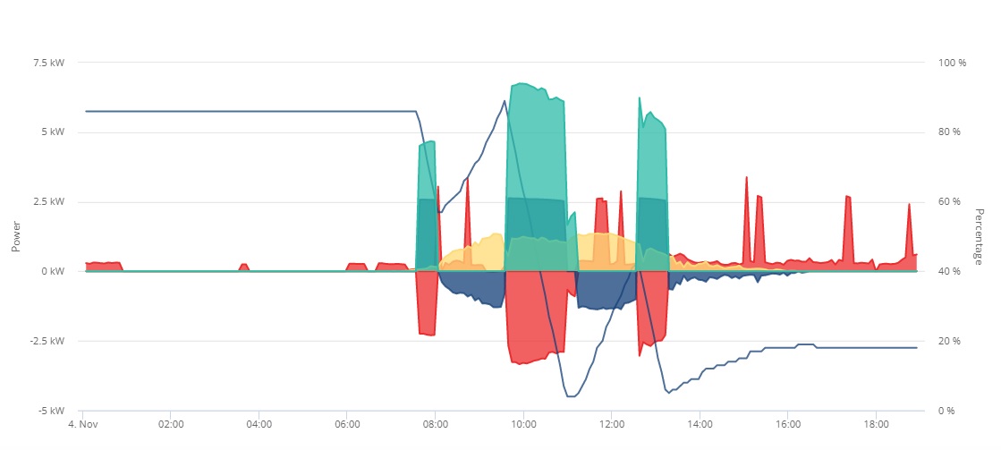
sbird In your power graph, values below the line (-ve kW) are import from grid and battery charge and values above the line are home consumption and solar generation. Just before 8am, it looks like there was a period of grid import (2.2kW red) and battery discharge (2.7kW blue) to supply house load (green) of about 4.7kW. From 8am to about 9.30 your (presumably South East-facing) PV was charging your battery.

(BTW If you use the Full BB link from Flikr, you can embed the actual image)
Looking at this, it seems to make sense, except you said that there was no actual load, just portal data that you couldn't explain? It does look odd to have periods of grid export at night and afternoon. If the CT is the wrong way round, they the odd periods would actually be grid import; your pre-8am event would be a short battery charge and the house load would not exist.

S
#19 sbird

Tim
Checked all the isolators / circuit breakers and all ok.
Reset to Defaults and observered no change in behaviour

S
#20 sbird

Tim
I have even switched off everything else from the fuse box, so that there cannot be any load demand, but still get these periodic events. My assumption is that the "load", is a mis-calculated value based on the battery discharge and grid export (which is mis-interpreted as import)

S
#21 sbird

ap2u
This looks similar to the graphs I am seeing on my system.
My installers are very unresponsive, despite reporting the problem in much detail several weeks ago.
The location of the CT Clamp is not obvious to me, so difficult to judge how accessible it is

#22 dbt85

Something definitely looks off with your meter data chart Steve. All of the values should only go up over the course of the day as it is a cumulative value being charted against time. Your battery charge, discharge and solar values all dropped just before 12. Was that when you reset something to defaults or did anything in particular?

Try another copy of that data for us, hover the mouse over one of the lines which will add the shape key to each line helping to identify it for us, and then do a print screen rather than a snip to grab it.

I have also raised a feedback thing on the portal as them using nearly (but not quite exactly) the same colours for import/export and charge/discharge is frankly baffling. They clearly thought about it as the RGB codes are fractionally different, but never actually bothered to wonder WHY they should be different and then realise that making them so close so as to be identical to most is utterly pointless.

Regarding the CT clamps and their location, they'll almost certainly be right next to your electricity meter or your solar cabling and I doubt they put it inside the consumer unit itself. If you can get a photo of those locations we can point out the bit that might be wrong.

T
#23 Tim

dbt85 They clearly thought about it as the RGB codes are fractionally different

The chart has a key showing different symbols for the different lines (eg grid import/export), but they don't appear on the actual chart. Thanks for raising the feedback. As a colour-blind person, I can confirm that the charts are of no use whatsoever as they stand; differentiating data with colour just doesn't work for me unless the colours are very different (black, red, yellow, blue). Just don't go near brown or purple or green; they may as well all be black.

T
#24 Tim

sbird The location of the CT Clamp is not obvious to me, so difficult to judge how accessible it is

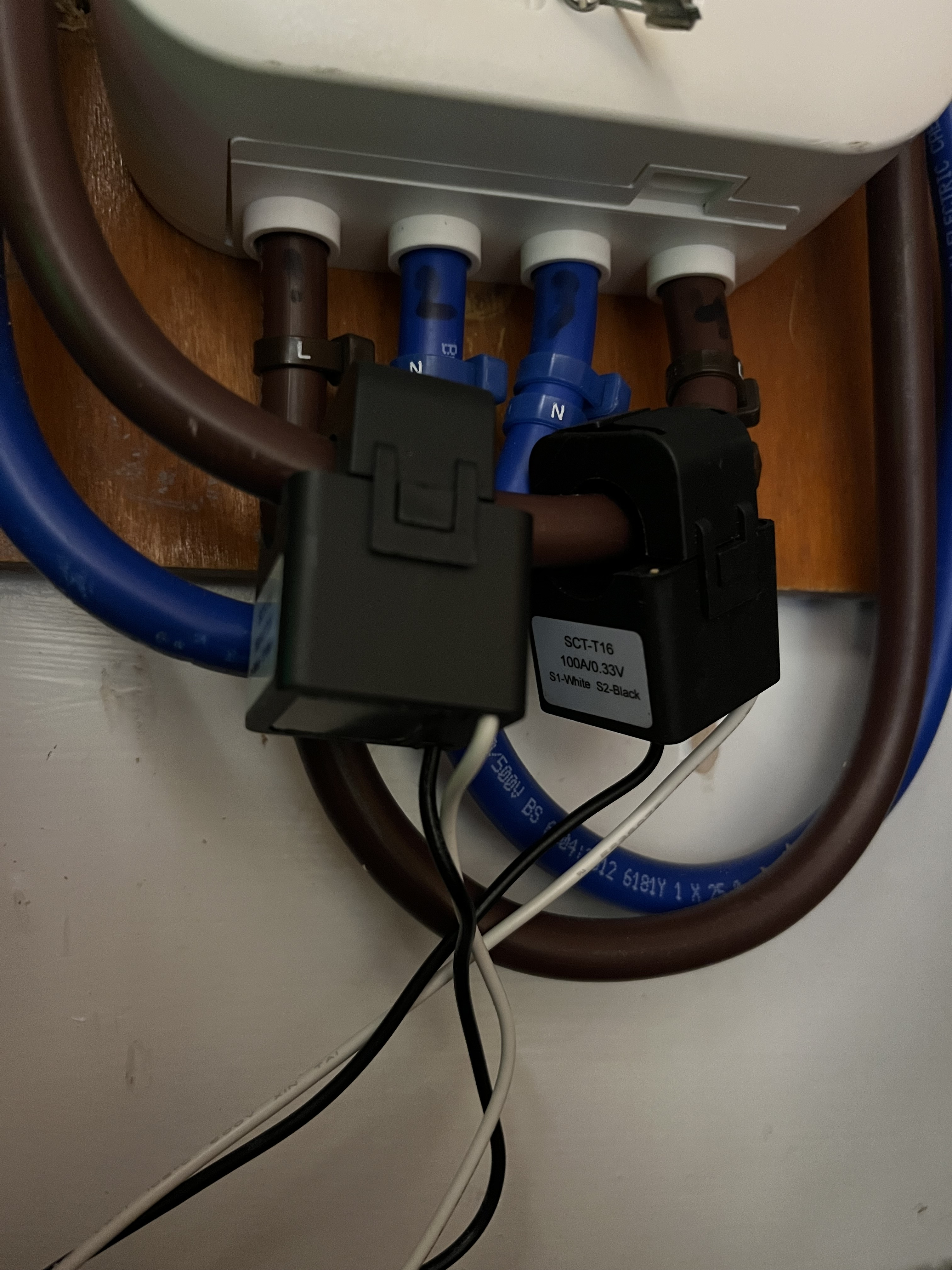
If you can find your OB115 and follow the grey cable or black and white wires, you'll find the CT on the far end.

Picture of our two CTs next to the supply meter.
Just unclip the catch at the side and turn it round to face the other way.

S
#25 sbird

Tim
Hi Tim,
I shall do some investigation tomorrow.
As a side question, why are there 2 clamps on the same cable?
My assumption is that the single clamp would provide:

  • grid import / export measurement
    I also assumed that if the system detects an request to import from then it would activate the inverter.
    Are these reasonable assumptions?
A
#26 anglefire

Probably for different devices. Solar uses one and ev another perhaps.

#27 TheDragon (GivEnergy)

anglefire or dual Hybrid

#28 positor1

or an energy diverter for immersion heater.. just ignore the fact it shows two.

#29 hoggy

Tim just has dual hybrids which ironically were the least supported install but appear to work best out of all the plant type setups!

#30 dbt85

sbird Yes that's how it works. The inverter sees current going to the grid and eventually wakes up and stores it in the battery. If it then detects current coming in from the grid it will wake up and discharge the battery. You may have multiple clamps depending on your setup. An Eddi solar diverter device for example will also measure import and export with one of those clamps.

#32 TheDragon (GivEnergy)

Tim think it's the combining of the data and sharing EM115s that's throwing the issues

T
#33 Tim

sbird Just saw on another thread that the OB115 looks to have a solid core CT as an option. If that's the case with yours, then swapping the CT round requires a little more circumspection. If it's a split core, then it will be OK to unclip it and turn it to face the other way.

Ideally, my suggestion would be to get your installer back to sort it all out. Commissioning checks should have caught a CT being the wrong way round.

S
#34 sbird

Tim
It has been a month and the installer has not responded to my weekly emails.
However, with your help I now have a much better idea of problem. With some qualified help the CT Clamp has been located behind the Consumer Unit. It has now been reversed and I am now getting non-zero Load readings. I am going to collect data over the next 24 hours, comparing it with the output of the Smart meter, to see if is behaving correctly.

Many thanks for everyones help.

#35 dbt85

Were you able to get a photo? There should be an arrow on the clamp and it helps indicate which way it should go assuming it is connected to the Line and not the Neutral.

T
#37 Tim

sbird From your photos, it does look to have been fitted correctly, pointing in the direction of grid import (from meter to consumer unit). What about the black and white terminations?

Looks like white goes to the left-hand terminal and black to the other.

#38 TheDragon (GivEnergy)

sbird CT clamps point towards the CU (Load)
Grid would be away from grid, Solar would be away from the PV towards teh CU & Grid.

Easiest way is always towards the load. So in your 2nd photo, arrow would be down to point at teh master breaker)

S
#39 sbird

Here is a couple of wider images of the Consumer Unit, which also shows the feed from the Inverter / Battery, cables coming up from the Grid Meter and the black/white wires going into the OB115.

https://www.flickr.com/photos/64044263@N04/shares/4U458ZFC4q

https://www.flickr.com/photos/64044263@N04/shares/2F48i6EX1H

Since reversing the Clamp I am getting:

  • non-zero load measurements
  • grid import measurements consistent with the load (no massive spikes of load / discharge)
  • battery discharge in response to the load

https://www.flickr.com/photos/64044263@N04/shares/5D50745z9r

I am much happier now

#40 Simon_C

Great that the metering is now working, but concerning with other aspects of that consumer unit.

1/ I thought that MCBs/RCBOs from different manufacturers were not supposed to be mixed on one busbar due to differences in sizing and alignment.
2/ Should the Live feed to the OB115 not be protected by something smaller than a C20 Amp RCBO, more like a 6 Amp? You do not have room for another breaker in there, so not sure what the solution would be.

Just my thoughts, and I am sure others will have their own ideas.

S
#41 sbird

Simon_C
I am not qualified to comment, but I would hope that the Installation Electrician knew what he was doing. If this a violation of the Wiring Regulations I would like to know so that I can follow up with the installer.

T
#42 Tim

sbird I think that you could probably find any number of sparkies who would find fault with what has been done. IMO it's not best practice and looks a bit untidy but unless they changed all the MCBs to the same make as the consumer unit (at your cost, you'd be thrilled to hear), and tidied up the installation to make it all neat (also at your cost), it's hard to retrofit additional circuits where someone else has already been. A competent electrician will leave the job safe, albeit at a standard less than a test-piece for his/her exams. On the other hand, if you had asked a sparkie to replace you consumer unit with a new one with new MCBs/RCBOs and it looked like that, you might have a stern word with them and suggest they buck their ideas up.

#43 TheDragon (GivEnergy)

sbird

At least he used an RCBO, mess aside. Also dont like that bare busbar

#44 Simon_C

TheDragon (GivEnergy) , there always seems to be a debate in the UK as to whether an RCBO is required in the consumer unit rather than a simple MCB when feeding a GivEnergy inverter.

As per this GivEnergy RCD Declaration, it is not necessary unless otherwise specified (which may be the case in the UK). And even if an RCBO is fitted, GivEnergy recommend that a Type A 100mA RCD is fitted. This Proteus one has a trip level of 30 mA, the same as the GivEnergy inverter.

https://kb.givenergy.cloud/article.php?id=63&oid=1

The consumer unit RCBO will provide RCD protection for the cable to the inverter in case it is damaged. The photos by the OP look like the cable only extends to the local isolator, the EmLite meter, then probably back through the wall to the inverter, so how likely is the cable to be damaged.
The GivEnergy inverter will also be monitoring the solar PV DC circuit as well as the battery DC circuit for earth leakage, so will shutdown if the 30 mA level is detected.
It is not recommended to have 2 RCD devices with the same trip levels (30 mA in this case) in line with each other as there is no discrimination between them.
As long as there is no nuisance tripping though it should be fine.

#45 positor1

as far as i recall, a sparkie can fit mcb;;s rcbo;;s of different makes but he/she then assumes the responsibilities from the manufacturer. ie any failure of components in that consumer unit.