EPS Max wattage in normal on grid conditions (Not a black out)

18 comments started 2023-03-28 last 2023-03-30
GivEnergy ProductsHybrid
M
#1 MESolar

Do any installers here have a confirmed figure for the maximum load that can be fed from the EPS terminal during normal operation (Not during a blackout). I have now been given 3 different figures from Givenergy:
No.1 - It acts as a bypass when there is no blackout so any amount can be added to the terminal but if the load is over 3.6kw under blackout conditions the inverter will trip.
No. 2 - Even when the grid supply is available the inverter will trip if the load exceeds 5kw
N0.3 - Only 3.6kw can be supplied whether the grid supply is available or not (battery dependent)

If anyone has an confirmed experience in regards to this it would be greatly beneficial.
#2 THALL

Which inverter do you have?

But the Gen 2 5kw has 3.6kw max so will need to stay under that. Again also depends on the battery connected to it

M
#3 MESolar

THALL

Yes it is the 9.5kwh battery so under black out conditions the limit would be 3.6kw I wanted to confirm that this is still the limit even during non blackout conditions when the grid supply is available.

T
#4 Tim

MESolar Check out this from their KB. I think the answer is that it's not straighforward. If there's no PV, then it's down the how much power your battery can supply the inverter and what the inverter maximum DC-AC conversion is. Whatever that value, you can add whatever PV you can pull and add it to the battery output, but the total is limited to the inverter nominal output. Thus, if you had 5kW PV to an HY5, all of the load could be supplied from PV. If the load reduced to 3kW, you should be able to charge the battery at 2kW, for 5kW PV.

However, you would never size your EPS based on the maximum potentially available, you'd keep load below that available from battery.

M
#5 MESolar

Thanks Tim, I just had a call from Dan at Givenergy and he said the safest way is to limit the load on the EPS terminals to 3.6kw (Or max discharge from the battery like you said) so that`s the figure I will take forward for dedicated circuits.

A
#6 alan_johnston

The EPS output cable should have overload protection which will trip if the EPS circuit takes more than the inverter can safely supply. If this is in circuit when grid running it will still trip and thus will limit what the grid can supply to the EPS circuit.

R
#7 Rubikcube

In a typical installation the Inverter is supplied from a 20A breaker in a consumer unit. This effectively limits the power to 4.6kW.

If you were doing a timed charge at 3.6kW that only leaves 1kW for the EPS before you risk tripping the supply breaker.

T
#8 Tim

Rubikcube I think that any timed charge would be limited by what the inverter could supply and since AFAIAA the inverter always prioritises house demand over charging, I would expect the inverter to pass, say 2kW to the EPS from grid and use the surplus 1.6kW for battery (for an AC3 anyway). For an HY5, the connection to consumer unit would be protected by a 32A MCB and so the charge to battery would be less limiting.

#9 hoggy

The max EPS wattage will be essentially dictated by the weakest link inside the inverter. As such given the rating on the battery backup side I'd personally use that as the maximum that can be drawn during "normal" operation given that's what will have been in mind when specifying internal components.
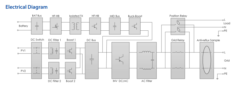
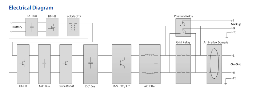
For anyone that cares the EPS output is linked as below to one side or the other of the Grid relay depending on if Grid is present or not:

Hybrid:

AC Coupled:

#10 Maxwell

MESolar That's not a good look from GE if they can't provide an accurate statement on their own equipment capability. It appears to me that with the gen 2, linked below that the output from the primary and backup are the same and that will be whether in normal mode with grid connected or in island mode when the grid fails. But, when the grid fails you face the risk of tripping the inverter if the house is pulling more than 3.6kWh. Or is there some other characteristics that are missing from their data sheet that impact this ?
https://www.givenergy.co.uk/pdfs/products/datasheets/giv-hy-3-6-gen-2.pdf

#11 Maxwell

hoggy Thanks for diagrams. So, for the hybrid inverters like the gen2 then under normal operation the house is supplied from the terminals marked "grid" and when incoming mains to the house fail the inverter switches the output to the terminals marked "load" ? Is that a correct interpretation of how it works ?

#14 Maxwell

SteveCook So, under normal operation the house is supplied from the "grid" terminals which are connected to the "load" terminals and when the mains lecky fails the inverter disconnects the inverter output from the "grid" terminals whilst maintaining the output to the "load" terminals ?

S
#15 SteveCook

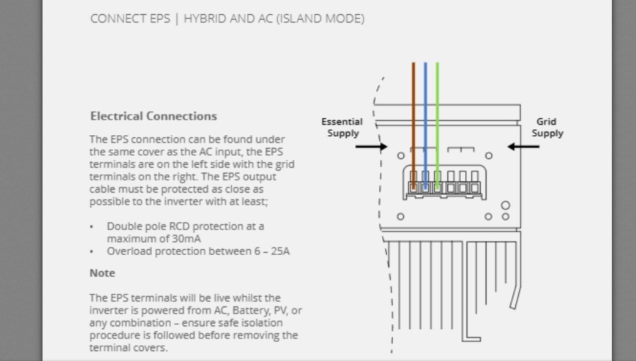
Under normal circumstances on my drawings, the main house CU is fed via the grid terminals. When grid fails they go off.

Under normal circumstances on my drawings the essential house CU is fed via the EPS terminals which are also live. When grid fails, they go off for about 5 seconds and then back on (though GE can set this to uninterrupted if you want)

My essential CU is low wattage stuff that I want all the time. Fridge ,freezer, router, smoke alarms, burglar alarm, gas boiler, lounge lights and lounge power (TV and Sky box). On grid failure we can sit in warm lounge and watch TV

#16 hoggy

Maxwell those are from Gen 1 (technical Gen 1 “OEM design”) but I can’t see why they would diverge significantly for Gen 2.
EPS terminals are essentially bridged from the input side to the inverter.
This does mean you are ultimately limited to the recommended MCB sizes for your inverter (normally 20A - 32A)

S
#17 SteveCook

The AC input to the inverter is also the AC output when their is enough solar and/or in export mode and goes back to the main house CU. That is called GRID SUPPLY

#18 hoggy

Yeah probably should have mentioned that on the diagram where it says Load/backup it means essential supply terminals….translation thing.

It doesn’t really matter for the application but I would be curious if enabling UPS mode changes how the relays are setup. I suspect that the “position” relay is reversed in UPS mode and the faster switching is achieved by dropping the Grid relay out (rather than normal non UPS mode where the grid relay opens, waits 5sec then switches the position relay over…anyway enough of my rambling)