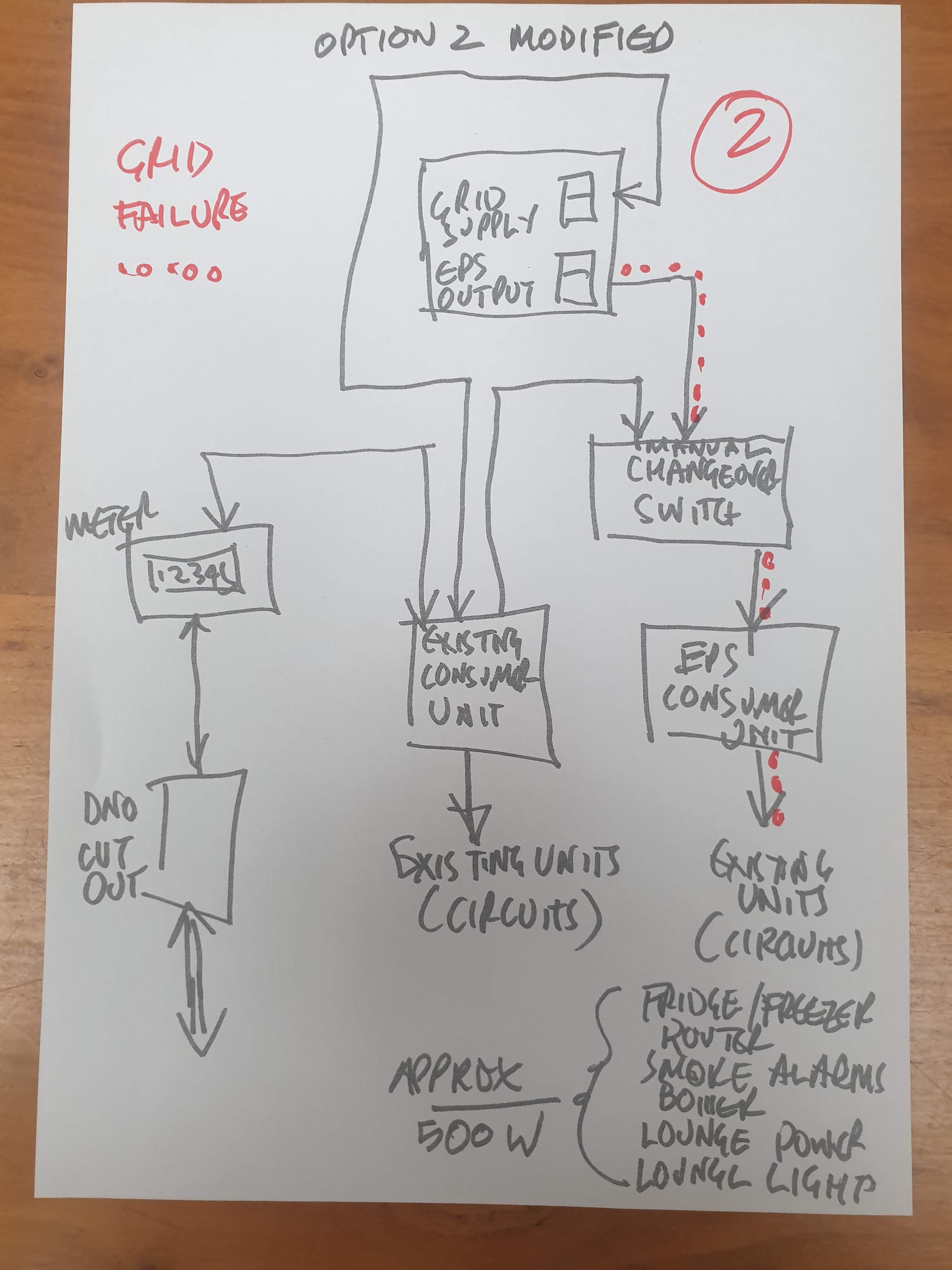
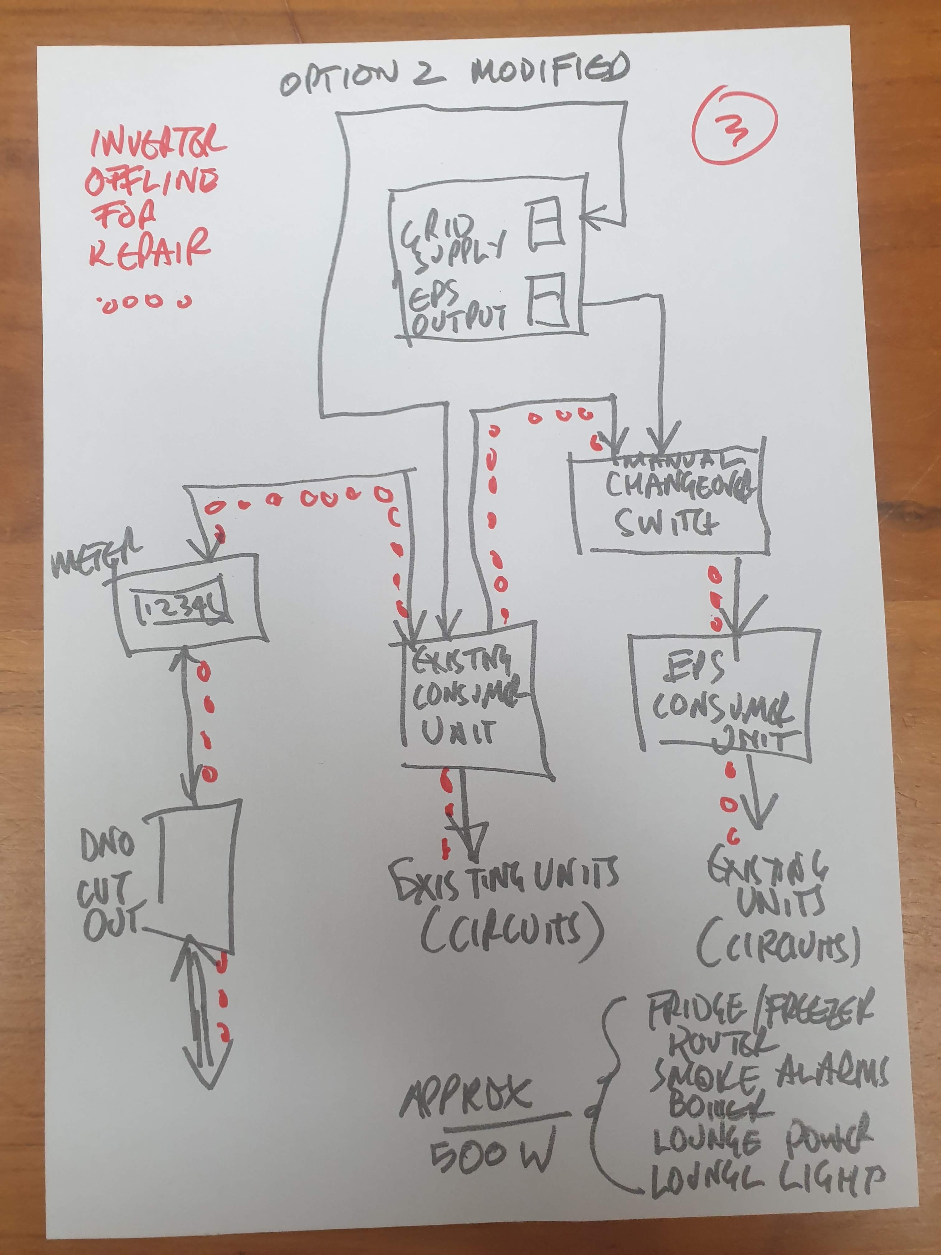
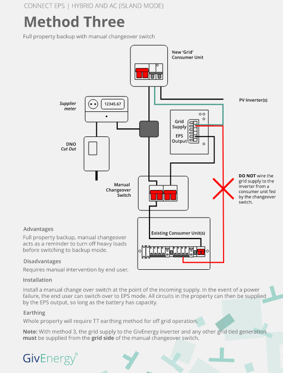
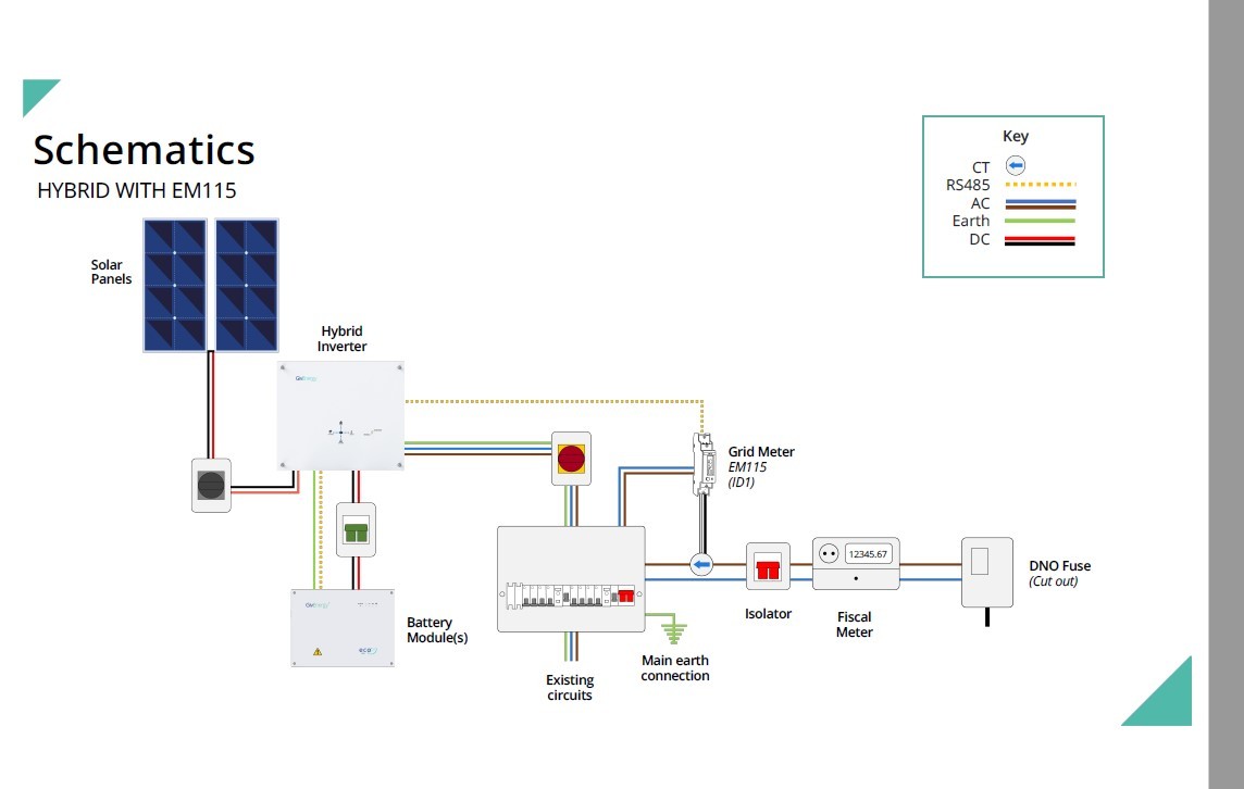
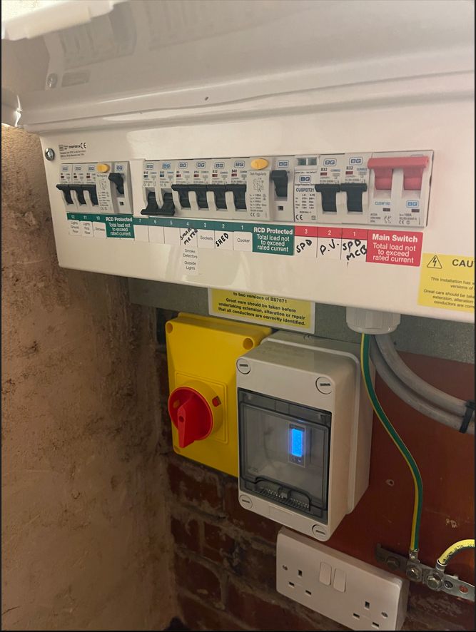
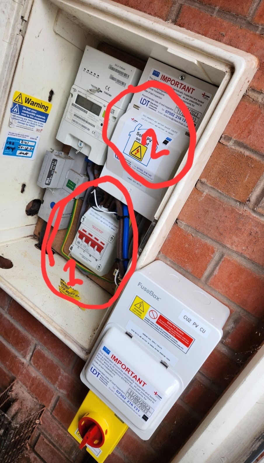
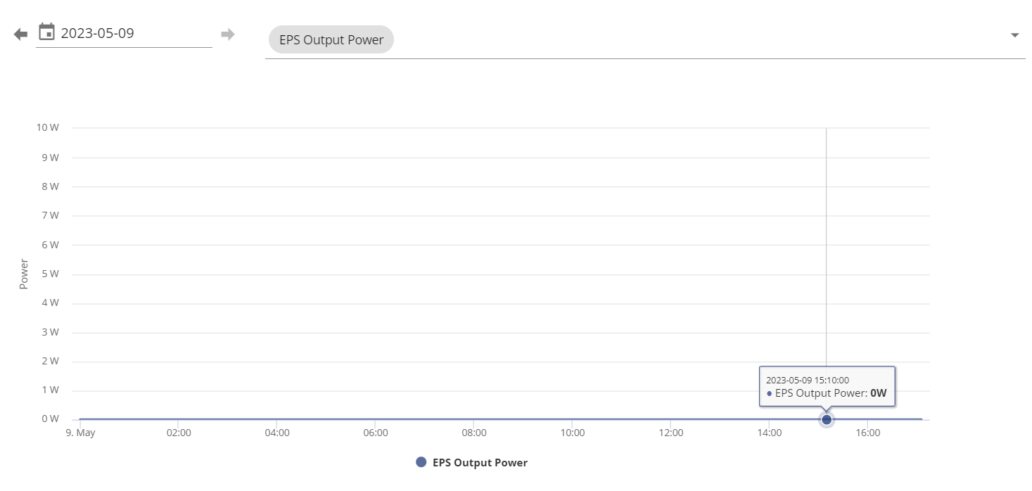
So I've been talking to GE via email over the last few days and they have been saying I do need an auto changeover switch, but never explained why. As I was going back and forth with them I asked what the difference between method 1 and 2 in the documentation was then if I wanted a method 2 setup but there is no auto changeover switch shown or mentioned for that method. They then came back saying:
No method 2 on the documentation does not require a changeover switch, it is essentially the same as the socket method but supplies a sub board that goes directly to the circuits themselves.
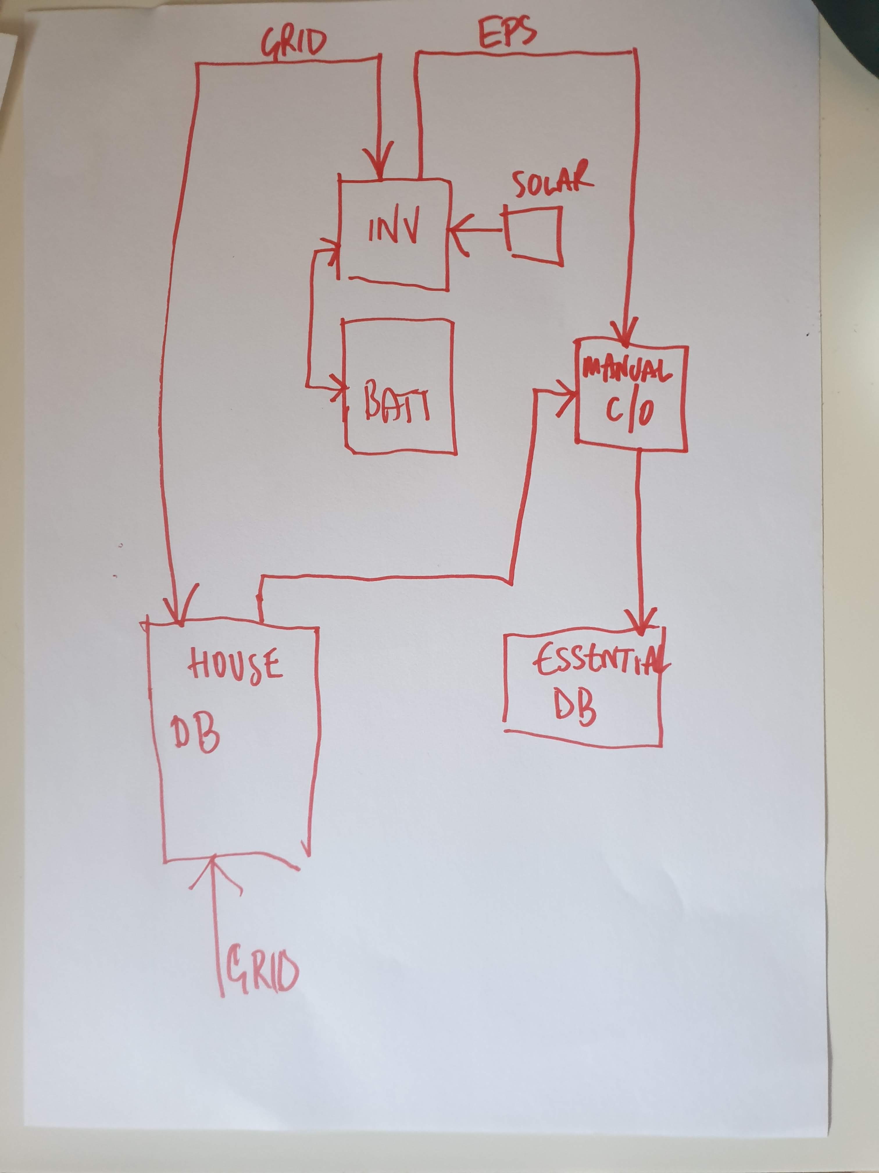
If the EPS is supplying the main distribution board a change over switch (either manual or automatic) would be required and the inverter would need to be supplied from a sub board.
However my installer has just been on the phone to GE and they have said an auto changeover switch is required for my setup. It feels like GE don't actually know themselves, or are giving out conflicting information on what the setup needs to be.
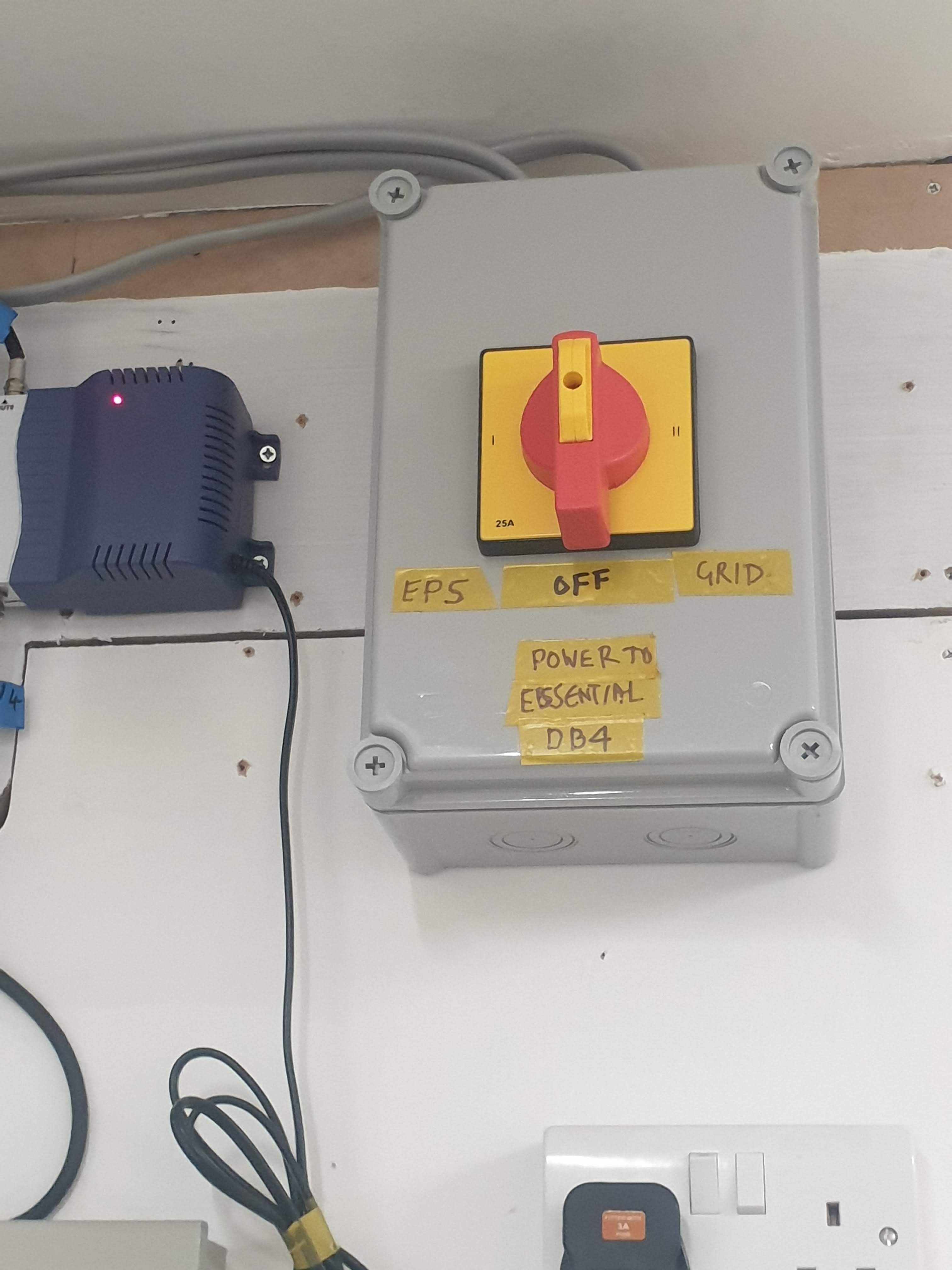
So I'm getting an auto changeover switch installed when they come back, who knows if it's actually required or not. Personally I can't see what it does in the setup as it appears to duplicate the functionality already provided by the inverter, all be it in a different way.
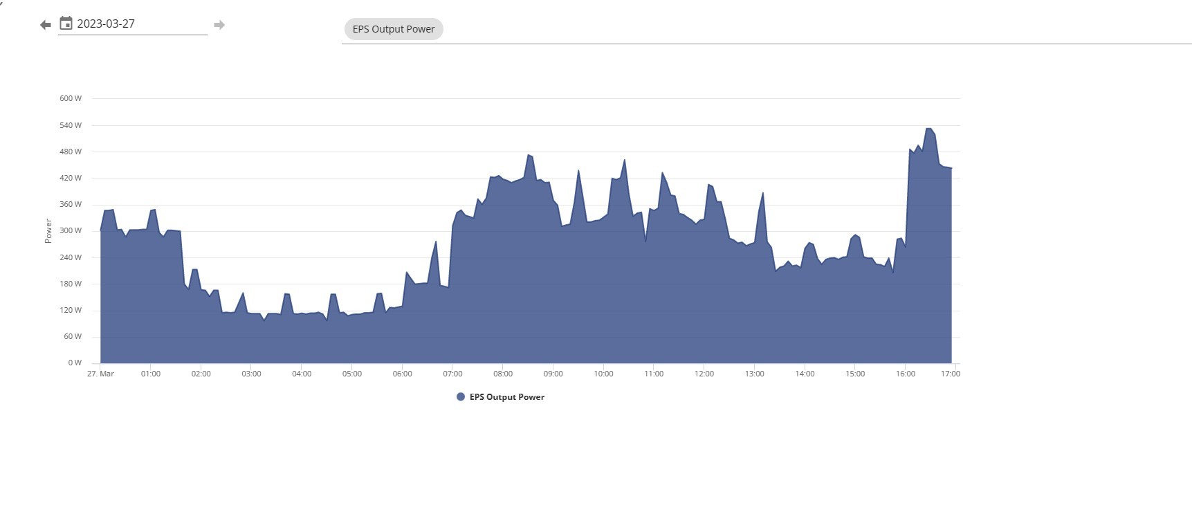
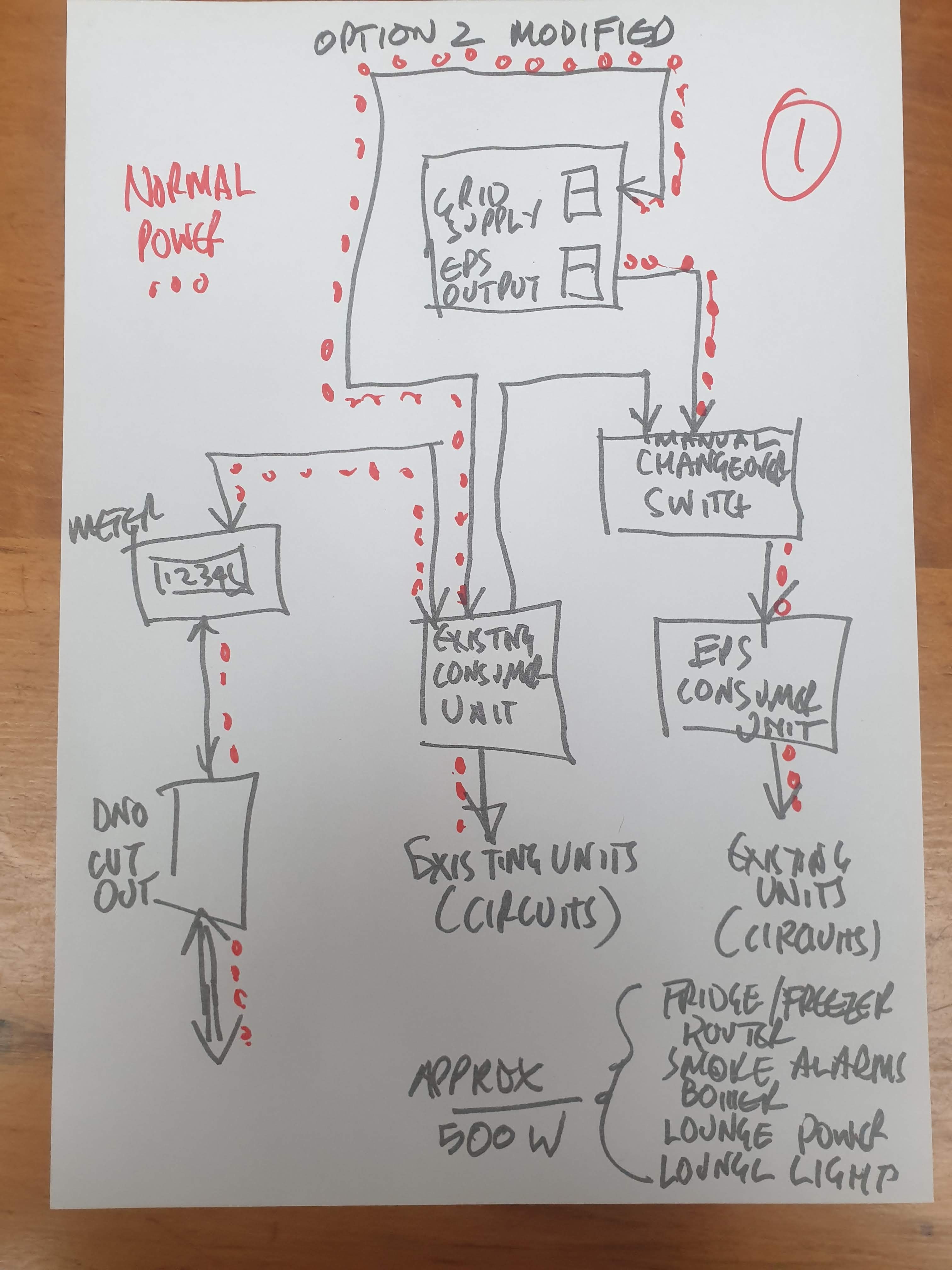
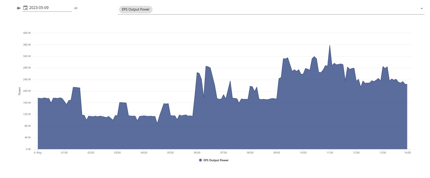
I guess the sub board will be powered by the mains connected circuit during normal operation, then during a power cut would auto switch over to be powered by the EPS output of the inverter. Rather than being powered by the EPS output on the inverter all of the time. Maybe they are worried about the load potentially being too great for the EPS output as potentially we could plug in some power hungry devices into a socket connected to the EPS. Obviously this is all hypothetical as I don't actually know how they are going to wire things up until they come and actually do it.